
Page 503 - Automotive Engineering Powertrain Chassis System and Vehicle Body
P. 503
Modelling and assembly of the full vehicle C HAPTER 15.1
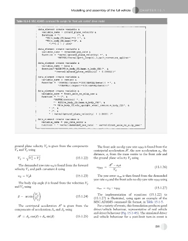
Table 15.1-5 MSC.ADAMS command file sample for ‘front axle control’ driver model
ground plane velocity V g is given from the components The front axle no-slip yaw rate u fNS is found from the
V x and V y using centripetal acceleration A , the yaw acceleration a z , the
p
q ffiffiffiffiffiffiffiffiffiffiffiffiffiffiffiffiffiffi distance, a, from the mass centre to the front axle and
2
V g ¼ V þ V y 2 (15.1.22) the ground plane velocity V g using
x
P
The demanded yaw rate u d is found from the forward A a z a
velocity V x and path curvature k using u fNS ¼ V g (15.1.26)
u ¼ V g k (15.1.23) The yaw error u err is then found from the demanded
d
yaw rate u d and the front axle no-slip yaw rate u fNS using
The body slip angle b is found from the velocities V y
and V g using
u err ¼ u u fNS (15.1.27)
d
!
V y The implementation of equations (15.1.22) to
b ¼ arcsin (15.1.24)
V g (15.1.27) is illustrated, using again an example of the
MSC.ADAMS command file format, in Table 15.1-5.
p
The centripetal acceleration A is given from the For a variety of events, this formulation produces good
components of acceleration A x and A y using driver/vehicle behaviour, representative of real vehicle
and driver behaviour (Fig. 15.1-45). The simulated driver
p
A ¼ A y cosðbÞþ A x sinðbÞ (15.1.25) and vehicle behaviour for a post-limit turn-in event is
511