
Page 505 - Automotive Engineering Powertrain Chassis System and Vehicle Body
P. 505
Modelling and assembly of the full vehicle C HAPTER 15.1
Body slip angle estimate
0.05
0.045
0.04
0.035
0.03
0.025
0.02
0.015
0.01
0.005
0
50 40 30 20 10 0 10 20 30 40 50
Body slip angle estimate
0.05
0.045
0.04
0.035
0.03
0.025
0.02
0.015
0.01
0.005
0
50 40 30 20 10 0 10 20 30 40 50
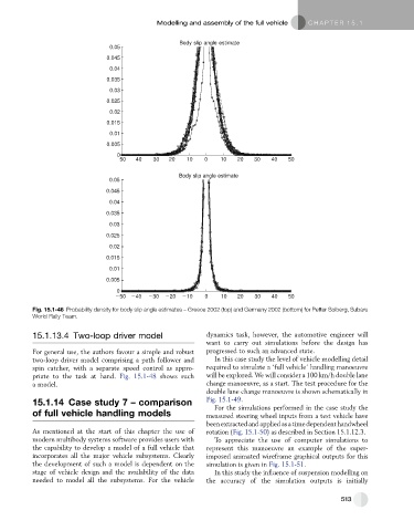
Fig. 15.1-46 Probability density for body slip angle estimates – Greece 2002 (top) and Germany 2002 (bottom) for Petter Solberg, Subaru
World Rally Team.
15.1.13.4 Two-loop driver model dynamics task, however, the automotive engineer will
want to carry out simulations before the design has
For general use, the authors favour a simple and robust progressed to such an advanced state.
two-loop driver model comprising a path follower and In this case study the level of vehicle modelling detail
spin catcher, with a separate speed control as appro- required to simulate a ‘full vehicle’ handling manoeuvre
priate to the task at hand. Fig. 15.1-48 shows such will be explored. We will consider a 100 km/h double lane
a model. change manoeuvre, as a start. The test procedure for the
double lane change manoeuvre is shown schematically in
15.1.14 Case study 7 – comparison Fig. 15.1-49.
For the simulations performed in the case study the
of full vehicle handling models measured steering wheel inputs from a test vehicle have
been extractedand applied asatimedependenthandwheel
As mentioned at the start of this chapter the use of rotation (Fig. 15.1-50) as described in Section 15.1.12.3.
modern multibody systems software provides users with To appreciate the use of computer simulations to
the capability to develop a model of a full vehicle that represent this manoeuvre an example of the super-
incorporates all the major vehicle subsystems. Clearly imposed animated wireframe graphical outputs for this
the development of such a model is dependent on the simulation is given in Fig. 15.1-51.
stage of vehicle design and the availability of the data In this study the influence of suspension modelling on
needed to model all the subsystems. For the vehicle the accuracy of the simulation outputs is initially
513