Page 520 - Automotive Engineering Powertrain Chassis System and Vehicle Body
P. 520
Terminology and overview of vehicle structure types    C HAPTER 16.1


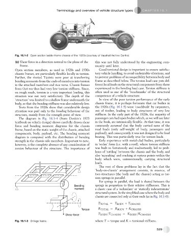
           Fig. 16.1-2 Open section ladder frame chassis of the 1920s (courtesy of Vauxhall Archive Centre).
           (c) Shear force in a direction normal to the plane of the  this was not fully understood by the engineering com-
              frame.                                          munity until later.
           Open section members, as used in 1920s and 1930s     Good torsional design is important to ensure satisfac-
           chassis frames, are particularly flexible locally in torsion.  tory vehicle handling, to avoid undesirable vibrations, and
           Further, the riveted T-joints were poor at transferring  to prevent problems of incompatibility between body and
           bending moments from the ends of members into torsion  frame as described below. The torsion load case puts dif-
           in the attached members and vice versa. Chassis frames  ferent local loads on the structural components from those
           from that era thus had very low torsion stiffness. Since,  experienced in the bending load case. Torsion stiffness is
           on rough roads, torsion is a very important loading, this  often used as one of the ‘benchmarks’ of the structural
           situation was not very satisfactory. The depth of the  competence of a vehicle structure.
           ‘structure’ was limited to a shallow frame underneath the  In view of the poor torsion performance of the early
           body, so that the bending stiffness was also relatively low.  chassis frame, it is perhaps fortunate that car bodies in
             Texts from the 1920s show that considerable design  the 1920s (Fig. 16.1-5) were ‘coachbuilt’ by carpenters,
           attention was paid only to the bending behaviour of the  out of timber, leading to body structures of very low
           structure, mainly from the strength point of view.  stiffness. In the early part of the 1920s, the majority of
             The diagram in Fig. 16.1-4 (from Donkin’s 1925   passenger cars had open bodies which, as we will see later
           textbook on vehicle design) shows carefully drawn shear  in the book, are intrinsically flexible. At that time, it was
           force and bending moment diagrams for the chassis  commonly assumed that the body carried none of the
           frame, based on the static weight of the chassis, attached  road loads (only self-weight of body, passengers and
           components, body, payload, etc. The bending moment  payload), and consequently it was not designed to be load
           diagram is compared with the distribution of bending  bearing. This was particularly true for torsion loads.
           strength in the chassis side members. Important to note,  Early experience with metal-clad bodies, particularly
           however, is the complete absence of any consideration of  in ‘sedan’ form (i.e. with a roof), where torsion stiffness
           torsion behaviour of the structure. The importance of  was built in fortuitously and inadvertently, led to prob-
                                                              lems of ‘rattling’ between the chassis and the body, and
                                                              also ‘squeaking’ and cracking at various points within the
                                                              body which were, unintentionally, carrying structural
                                                              loads.
                                                                The root of these problems lay in the fact that the
                                                              ‘body-on-chassis’ arrangement consists, in essence, of
                                                              two structures (the body and the chassis) acting as tor-
                                                              sion springs in parallel.
                                                                For springs in parallel, the load is shared between the
                                                 Bending      springs in proportion to their relative stiffnesses. This is
                                                 moment       a classic case of a ‘redundant’ or ‘statically indeterminate’
                                                              structural system. In the simplified case where the body and
                                                              chassis are connected only at their ends (as in Fig. 16.1-6):

                                                                T TOTAL ¼ T BODY þ T CHASSIS

                                                     Torque     K TOTAL ¼ K BODY þ K CHASSIS
                                                                T BODY =T       ¼ K BODY =K
                                           Shear force                  CHASSIS            CHASSIS
           Fig. 16.1-3 Grillage frame.                        where T ¼ torque and K ¼ torsional stiffness.


                                                                                                     529

