
Page 522 - Automotive Engineering Powertrain Chassis System and Vehicle Body
P. 522
Terminology and overview of vehicle structure types C HAPTER 16.1
Side member
Front
Dash
seating pillar
Door Bonnet
pillar support
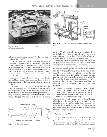
Fig. 16.1-7 Construction details of a timber framed ‘fabric
body’.
Fig. 16.1-5 Car body manufacture in the 1920s (courtesy of
Vauxhall Archive Centre).
together. This led to much greater stiffness in the body,
particularly for torsion, because the steel panels were
quite effective locally in shear. The overall configuration
deliberate use of flexible materials for the outer skin of
the body (Fig. 16.1-7). still remained as the ‘body-on-separate- chassis’.
It will be seen later in the book that closed shell In the 1930s the subfloor chassis frame was still made
structures such as closed car bodies are very effective in of open section members, riveted together, and it was
torsion, with the outer skin subjected locally to shear. In still regarded as the ‘structure’ of the vehicle.
order to keep torsion stiffness (and hence loads) small, From the ‘springs in parallel’ analogy, however, it can
flexible materials such as fabric were used to form the be seen that a much greater proportion of the load was
outer skin of the body. In Europe, the ‘Weymann fabric now taken through the body, owing to its greater stiff-
saloon’ body was a well-known, and much copied, ness. This led to problems of ‘fighting’ between the body
example of this. and the chassis frame (i.e. rattling, or damage to body
An alternative approach was to use very thin alumin- mounts caused by undesired load transfer between the
ium cladding with deliberate structural discontinuities at body and the chassis). Several approaches were tried to
key points to relieve the build-up of undesired stresses in overcome this problem. These were used both in-
dividually and in combination with each other. They
the body.
included:
The fabric-covered wood-framed car body was not
amenable to large-scale mass production. As the 1920s (a) Flexible (elastomer) mountings were added
gave way to the 1930s, the requirements of high volume between the chassis frame and the body. Laterally
production led to the widespread use of pressed steel car spaced pairs of these mountings acted as torsion
body technology. The bodies were formed out of steel springs about the longitudinal axis of the vehicle
sheets, stamped into shape, and welded or riveted between the chassis and the body.
Consider a pair of body mounts positioned on either side
of the body. If the linear stiffness of the individual elas-
tomer body mounts is K LIN , and they are separated lat-
Body stiffness K BODY erally by body width B (see Fig. 16.1-8), then the
torsional stiffness K MOUNT of the pair of mounts about
Torque Torque the vehicle longitudinal axis is:
in out
2
K MOUNT ¼ K LIN B =2
As used in 1930s vehicles this, in effect, made the ‘load
Chassis frame stiffness K CHASSIS path’ through the body more flexible, because the pairs
of soft elastomer mounts and the body formed a chain
Fig. 16.1-6 Springs in parallel. of ‘springs in series’ (see Fig. 16.1-9). For such a system,
531