
Page 524 - Automotive Engineering Powertrain Chassis System and Vehicle Body
P. 524
Terminology and overview of vehicle structure types C HAPTER 16.1
A 24" B 24" C 57" D 56"
E
6283 LBS. 8378 LBS.
FT./DEG. FT./DEG. 6283 LBS. FT./DEG. 2960 LBS. FT./DEG.
29800 LBS. FT./DEG./FT. RUN 13830 LBS. FT./DEG./FT. RUN
2566 LBS. 17450 LBS.
FT/DEG./FT. RUN FT/DEG./FT. RUN
DEFLECTION DIAGRAM 13/64"
39/64" 31/64" 25/64" DEFL. @ 75" RADIUS : 1/4° TWIST(APP .)
TOTAL DEFLECTION @ 75" RADIUS 1" : 5/16" DEFL.
= 39/64" −1290 LBS. FT./DEGREE
= 13550 LBS. FT./DEGREE/FT.RUN
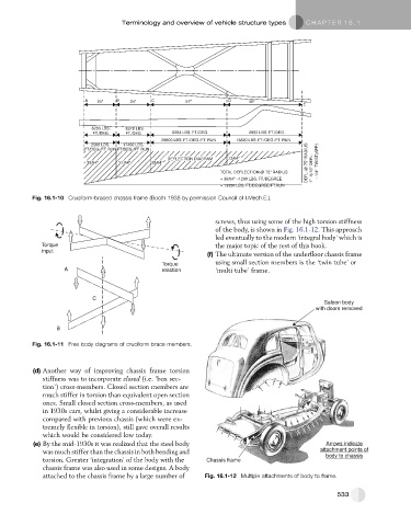
Fig. 16.1-10 Cruciform-braced chassis frame (Booth 1938 by permission Council of I.Mech.E.).
screws, thus using some of the high torsion stiffness
of the body, is shown in Fig. 16.1-12. This approach
led eventually to the modern ‘integral body’ which is
Torque the major topic of the rest of this book.
input
(f) The ultimate version of the underfloor chassis frame
Torque using small section members is the ‘twin tube’ or
A reaction ‘multi tube’ frame.
C
Saloon body
with doors removed
B
Fig. 16.1-11 Free body diagrams of cruciform brace members.
(d) Another way of improving chassis frame torsion
stiffness was to incorporate closed (i.e. ‘box sec-
tion’) cross-members. Closed section members are
much stiffer in torsion than equivalent open section
ones. Small closed section cross-members, as used
in 1930s cars, whilst giving a considerable increase
compared with previous chassis (which were ex-
tremely flexible in torsion), still gave overall results
which would be considered low today.
(e) By the mid-1930s it was realized that the steel body Arrows indicate
was much stiffer than the chassis in both bending and attachment points of
body to chassis
torsion. Greater ‘integration’ of the body with the Chassis frame
chassis frame was also used in some designs. A body
attached to the chassis frame by a large number of Fig. 16.1-12 Multiple attachments of body to frame.
533