
Page 523 - Automotive Engineering Powertrain Chassis System and Vehicle Body
P. 523
CHAP TER 1 6. 1 Terminology and overview of vehicle structure types
A common solution was the use of cruciform bracing.For
this, a cross-shaped brace, made usually of open channel
section members, was incorporated into the chassis
frame as shown in Fig. 16.1-10. It was necessary for the
Torque T Body
Twist θ ends of this to be well connected, in shear, to the chassis
side members.
Fig. 16.1-11 shows how the cruciform brace works as
a torsion structure. On the left, the ‘input torque’ is fed
Body mount
linear stiffness in as a couple consisting of two equal and opposite forces.
K LIN This couple, or torque, is reacted by the couple com-
Body mount separation Chassis frame posed of the equal and opposite forces on the right-hand
B side of the diagram.
The exploded view shows the local loads in the in-
Fig. 16.1-8 Laterally positioned pair of body mountings. dividual members. Member A has vertical loads down-
ward at both ends. These are reacted by the upward force
at point C. This in turn is reacted by an equal and op-
posite force at point C on member B, and the loads in
the overall flexibility (the reciprocal of stiffness) is the member B are a mirror image of those in A.
sum of the individual flexibilities. As a result, the overall Although the overall effect is a torsion carrying
stiffness is lower than that of the individual elements in structure, the individual members (A and B) are subject
the series. Thus,
only to bending and shear forces. Hence it was possible to
use open sections. It is essential that there is a good,
1=K TOTAL ¼ K F-MOUNT þ 1=K BODY þ 1=K R-MOUNT
continuous, bending load path in both members A and B
at point C (point of maximum bending moment).
where K ¼ torsion stiffness and 1/K ¼ torsional flexibility. By the mid-1930s, the need for reasonable torsion
Since the body-plus-mountings assembly was, struc- stiffness was well recognized. A paper of the time from
turally, still in parallel with the chassis, the effect of the which Fig. 16.1-10 is taken, gives overall torsion stiff-
reduced stiffness was to reduce the proportion of the ness values between 1000 and 1750 N m/deg. for vari-
torsion load carried by the body. ous cruciform-braced chassis frames. One of the best of
(b) The converse of the approach in (a) was to stiffen the cruciform-braced underfloor open section chassis
the chassis frame, thus encouraging it to carry was that of the Lagonda V12 of the late 1930s. The
more of the load. Open section, riveted chassis frame consisted entirely of a substantial cross brace,
frame technology was still the norm in the 1930s, with only small tie rods along the side to prevent
and so a method of increasing torsion stiffness, but ‘wracking’ distortion. Its torsion stiffness was measured
still using open section members, was needed. to be a little over 2000 N m/deg.
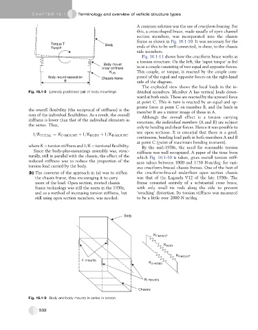
Body
K F-MOUNT
K BODY
K R-MOUNT
F-mounts
K CHASSIS
R-mounts
Chassis
Fig. 16.1-9 Body and body mounts in series in torsion.
532