
Page 555 - Automotive Engineering Powertrain Chassis System and Vehicle Body
P. 555
CHAP TER 1 6. 2 Standard sedan (saloon) – baseline load paths
Resolving forces vertically and by symmetry
00
P 00 11 þ P 00 26 P ¼ 0 (16.2.68)
8
16.2.5.6 Rear parcel shelf (10)
Resolving forces horizontally
00
2P 00 12 2P ¼ 0 (16.2.69)
9
16.2.5.7 Transverse floor beam (rear) (2)
As the inertia load from the rear seat passengers acts at
height h pr the vertical load on this member is:
Fig. 16.2-31 Baseline model (front structure) – braking loads.
P 00 ¼ F xpr h pr =2ðl 5 l Þ (16.2.70)
4
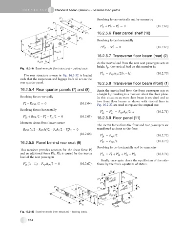
The rear structure shown in Fig. 16.2-32 is loaded 25
such that the suspension and luggage loads all act on the
rear quarter panel. 16.2.5.8 Transverse floor beam (front) (1)
16.2.5.4 Rear quarter panels (7) and (8) Again the inertia load from the front passengers acts at
a height h pf resulting in a moment about the floor plane.
Resolving forces vertically In this situation an extra floor beam is required and so
two front floor beams as shown with dashed lines in
00
P R ZXR =2 ¼ 0 (16.2.64) Fig. 16.2-33 are used to replace the original one:
8
Resolving forces horizontally 00 00
P 22 ¼ P 23 ¼ F xpf pf (16.2.71)
h =2l 10
00
P 00 þ R XR =2 P F =2 ¼ 0 (16.2.65)
10 9 xl 16.2.5.9 Floor panel (11)
Moments about front lower corner
The inertia forces from the front and rear passengers are
00
R ZXR l 2 =2 R XR hf=2 F h =2 P h 2 ¼ 0 transferred as shear to the floor:
xl l
9
(16.2.66) 00
P ¼ F =2 (16.2.72)
24 xpf
P 00 ¼ F xpr =2 (16.2.73)
16.2.5.5 Panel behind rear seat (9) 27
Resolving forces horizontally and by symmetry
00
This member provides reaction for the shear force P 8
00
00
00
and an additional force P 26 .P 26 is caused by the inertia P 00 13 ¼ P þ P 00 10 þ P 00 24 þ P 00 27 (16.2.74)
5
load of the rear passengers
Finally, once again check the equilibrium of the side-
00
P ðl 5 l Þ F xpr h pr =2 ¼ 0 (16.2.67) frame by the three equations of statics.
4
26
Fig. 16.2-32 Baseline model (rear structure) – braking loads.
564