
Page 552 - Automotive Engineering Powertrain Chassis System and Vehicle Body
P. 552
Standard sedan (saloon) – baseline load paths C HAPTER 16.2
Fig. 16.2-27 Baseline model (rear structure) – lateral loading.
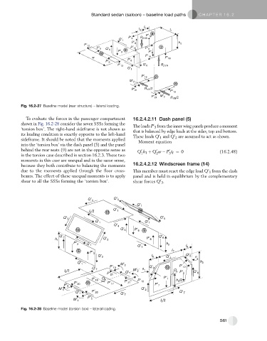
To evaluate the forces in the passenger compartment 16.2.4.2.11 Dash panel (5)
shown in Fig. 16.2-28 consider the seven SSSs forming the The loads P 3 from the inner wing panels produce a moment
0
‘torsion box’. The right-hand sideframe is not shown as that is balanced by edge loads at the sides, top and bottom.
its loading condition is exactly opposite to the left-hand These loads Q 1 and Q 2 are assumed to act as shown.
0
0
sideframe. It should be noted that the moments applied Moment equation
into the ‘torsion box’ via the dash panel (5) and the panel
behind the rear seats (9) are not in the opposite sense as Q h 1 þ Q w P t ¼ 0 (16.2.48)
0
0
0
in the torsion case described in section 16.2.3. These two 1 2 3 f
moments in this case are unequal and in the same sense,
because they both contribute to balancing the moments 16.2.4.2.12 Windscreen frame (14)
0
due to the moments applied through the floor cross- This member must react the edge load Q 1 from the dash
beams. The effect of these unequal moments is to apply panel and is held in equilibrium by the complementary
0
shear to all the SSSs forming the ‘torsion box’. shear forces Q 3 .
Fig. 16.2-28 Baseline model (torsion box) – lateral loading.
561