Page 551 - Automotive Engineering Powertrain Chassis System and Vehicle Body
P. 551

CHAP TER 1 6. 2       Standard sedan (saloon) – baseline load paths

               Resolving forces laterally                         Resolve forces horizontally
                                                                     0
                                                                    P ¼ P 0                               (16.2.40)
                 P 0 17  ¼ F ypr                      (16.2.33)      5    4
                                                                    The right-hand front inner wing panel has similar load
               16.2.4.2.4 Luggage beam (22)                       values but all are in the opposite sense giving similar
               By taking moments about one end                    equations.

                 P 0 18  ¼ F h =t r                   (16.2.34)   16.2.4.2.7 Front parcel shelf (6)
                        yl l
                                                                  This member is attached to the dash panel and the
               Resolving forces laterally
                                                                  windscreen frame at the front edge but with no attach-
                 P 0 19  ¼ F =2                       (16.2.35)   ment at the rear. Therefore, no lateral loads can be ap-
                        yl
                                                                                                             0
                                                                  plied. The forces from the inner wing panels P 4 are
                                                                                       0
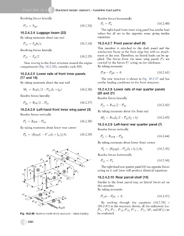
                 Now moving to the front structure around the engine  reacted by the forces P 7 acting on the sideframe.
               compartment (Fig. 16.2-26), consider each SSS.     By taking moments
                                                                     0
                                                                           0
                                                                    P w   P t ¼ 0                         (16.2.41)
               16.2.4.2.5 Lower rails of front inner panels          7     4 f
               (17 and 18)                                          The rear structure is shown in Fig. 16.2-27 and has
               By taking moments about the rear end               similar loading conditions to the front structure.
                                 0
                 M 1 ¼ R YF l 1 =2   P ðl 1 þ l pt Þ  (16.2.36)   16.2.4.2.8 Lower rails of rear quarter panels
                                 15
                                                                  (20 and 21)
               Resolve forces laterally
                                                                  Resolve forces laterally
                 P 0 20  ¼ R YF =2   P 0 15           (16.2.37)
                                                                    P 0 21  ¼ R YR =2   P 0 19            (16.2.42)
               16.2.4.2.6 Left-hand front inner wing panel (3)
                                                                  By taking moments about the front end
               Resolve forces vertically
                                                                      0
                                                                                     0
                                                                    M ¼ R YR l 2 =2   P ðl 2 þ l Þ        (16.2.43)
                                                                                            l
                                                                                     19
                                                                      2
                  0
                 P ¼ R ZYF   P 0 14                   (16.2.38)
                  3
                                                                  16.2.4.2.9 Left-hand rear quarter panel (7)
               By taking moments about lower rear corner
                                                                  Resolve forces vertically
                  0
                                  ðl
                 P ¼fR ZYF l 1   P 0 14 1 þ l pt Þg=h 1  (16.2.39)   0           0
                  4
                                                                    P ¼ R ZYR   P
                                                                     8           18                       (16.2.44)
                                                                  By taking moments about lower front corner
                                                                      0             0
                                                                    P ¼fR ZYR l 2  P ðl 2 þl 1 Þg=h 2     (16.2.45)
                                                                      9             18
                                                                  Resolve forces horizontally
                                                                    P 0 10  ¼ P 0 9                       (16.2.46)
                                                                    The right-hand rear quarter panel (8) has opposite forces
                                                                  acting on it and these will produce identical equations.
                                                                  16.2.4.2.10 Rear parcel shelf (10)
                                                                  Similar to the front parcel tray, no lateral forces act on
                                                                  this member.
                                                                  By taking moments
                                                                            0
                                                                     0
                                                                    P w   P t r ¼ 0                       (16.2.47)
                                                                            9
                                                                     12
                                                                    By working through the equations (16.2.28) –
                                                                  (16.2.47) in the sequence shown, all the unknowns (i.e.
                                                                                         0
                                                                                                            0
                                                                                                     0
                                                                                                0
                                                                                     0
                                                                            0
                                                                        0
                                                                                 0
                                                                   0
                                                                  P 1 . P 5 ,P 7 . P 10 ,P 12 ,P 14 . P 21 ,M 1 and M 2 ) can
               Fig. 16.2-26 Baseline model (front structure) – lateral loading.  be evaluated.
                    560
   546   547   548   549   550   551   552   553   554   555   556