
Page 549 - Automotive Engineering Powertrain Chassis System and Vehicle Body
P. 549
CHAP TER 1 6. 2 Standard sedan (saloon) – baseline load paths
1=K ¼ 1=K 2 þð1=K 1 þ 1=K 3 þ 1=K þ 1=K 5 Þ which act in addition to the vertical forces shown in
4
Fig. 16.2-2. In this section only these forces are consid-
¼ 1=5000 þ 4=50 000
ered and they should then be added to the force system
analysed in section 16.2.2.
Thus: K ¼ 3571 Nm/deg.
The overall torsion stiffness has been reduced to about
36% of the original value. It is thus of paramount im- 16.2.4.1 Roll moment and distribution at front
portance that all of the subassemblies have correct load- and rear suspensions
path design and that the connections between them are Taking moments about the vehicle centreline (see Fig.
structurally sound. 16.2-24) at the plane of the floor to obtain: roll moment
16.2.4 Lateral loading case M R ¼ F ypt h pt þ F ypf pf yl l
h þ F ypr h pr þ F h
When a vehicle travels on a curved path lateral forces are This is the moment due to the forces acting
generated due to centrifugal acceleration. Inertia forces through the centres of mass. This is balanced by the
act at the centres of mass of the components which tend vertical reactions at front and rear suspension mount-
to throw them away from the centre of turn. These are ing points:
balanced by lateral forces generated at the tyre to ground
M R ¼ R ZYF t þ R ZYR t r
f
contact points which are transferred to the structure of
the vehicle through the suspension. This condition is There are now unknowns, R ZYF and R ZYR , and only one
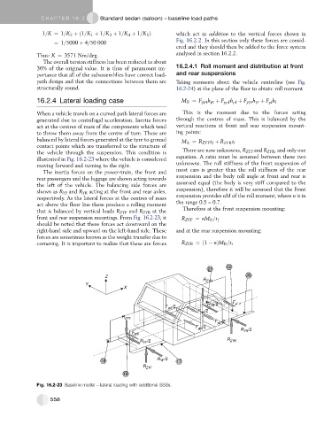
illustrated in Fig. 16.2-23 where the vehicle is considered equation. A ratio must be assumed between these two
moving forward and turning to the right. unknowns. The roll stiffness of the front suspension of
The inertia forces on the power-train, the front and most cars is greater than the roll stiffness of the rear
rear passengers and the luggage are shown acting towards suspension and the body roll angle at front and rear is
the left of the vehicle. The balancing side forces are assumed equal (the body is very stiff compared to the
shown as R YF and R YR acting at the front and rear axles, suspension), therefore it will be assumed that the front
respectively. As the lateral forces at the centres of mass suspension provides nM of the roll moment, where n is in
act above the floor line these produce a rolling moment the range 0.5 – 0.7.
that is balanced by vertical loads R ZYF and R ZYR at the Therefore at the front suspension mounting:
front and rear suspension mountings. From Fig. 16.2-23,it R ZYF ¼ nM R =t f
should be noted that these forces act downward on the
right-hand side and upward on the left-hand side. These and at the rear suspension mounting:
forces are sometimes known as the weight transfer due to
cornering. It is important to realize that these are forces R ZYR ¼ð1 nÞM R =t r
22
21
Z 20
R ZYR
Y
X
R YR /2 F yl
F ypf /2
F ypr /2
R ZYF
F ypr /2
F ypf /2
R YR /2
F ypt
R /2 R ZYR
YF
R /2
18 YF 17
R ZYF
19
Fig. 16.2-23 Baseline model – lateral loading with additional SSSs.
558