
Page 544 - Automotive Engineering Powertrain Chassis System and Vehicle Body
P. 544
Standard sedan (saloon) – baseline load paths C HAPTER 16.2
X
θ A θ C F VERTICAL ¼ 0. Q 2 þ Q 3 VERTICAL
Q 3V Q 5 VERTICAL þ Q 6 ¼ 0
H B Q 3H E Q 5H
G
Z
h 1 Q 5V h 2
16.2.3.6 Some notes on the standard
X sedan in torsion
L 5 (a) A knowledge of the shear stress s in the panels is
required. The panel thickness t must be chosen so that
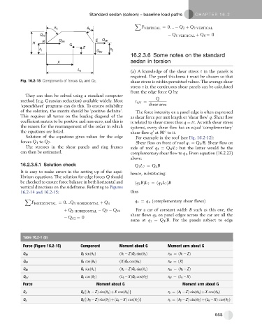
Fig. 16.2-15 Components of forces Q 3 and Q 5 . shear stress is within permitted values. The average shear
stress s in the continuous shear panels can be calculated
from the edge force Q by:
They can then be solved using a standard computer
Q
method (e.g. Gaussian reduction) available widely. Most s AV ¼
‘spreadsheet’ programs can do this. To ensure reliability shear area
of the solution, the matrix should be ‘positive definite’. The force intensity on a panel edge is often expressed
This requires all terms on the leading diagonal of the as shear force per unit length or ‘shear flow’ q. Shear flow
coefficient matrix to be positive and non-zero, and this is is related to shear stress thus q ¼ ts. As with shear stress
the reason for the rearrangement of the order in which systems, every shear flow has an equal ‘complementary’
the equations are listed. shear flow q at 90 to it.
0
Solution of the equations gives values for the edge For example in the roof (see Fig. 16.2-12):
forces Q 1 to Q 7 . Shear flow on front of roof q 1 ¼ Q 1 /B. Shear flow on
The stresses in the shear panels and ring frames side of roof q 4 ¼ Q 4 /L 7 but the latter would be the
can then be estimated. complementary shear flow to q 1 . From equation (16.2.23)
above:
16.2.3.5.1 Solution check Q 1 L 7 ¼ Q B
4
It is easy to make errors in the setting up of the equi- hence, substituting:
librium equations. The solution for edge forces Q should
be checked to ensure force balance in both horizontal and ðq 1 BÞL 7 ¼ðq L 7 ÞB
4
vertical directions on the sideframe. Referring to Figures
16.2-14 and 16.2-15: thus
X
F HORIZONTAL ¼ 0.Q 3 HORIZONTAL þ Q 4 q 1 ¼ q ðcomplementary shear flowsÞ
4
þ Q 5 HORIZONTAL Q 7 Q X1 For a car of constant width B such as this one, the
shear flows q 1 on panel edges across the car are all the
Q X2 ¼ 0
same at q 1 ¼ Q 1 /B. For the panels subject to edge
Table 16.2-1 (b)
Force (Figure 16.2-15) Component Moment about G Moment arm about G
Q 3 sinðq A Þ ðh 1 ZÞQ 3 sinðq A Þ r 3H ¼ðh 1 ZÞ
Q 3H
Q 3 cosðq A Þ ðXÞQ 3 cosðq A Þ r 3V ¼ðXÞ
Q 3V
Q 5 sinðq C Þ ðh 2 ZÞQ 5 sinðq C Þ r 5H ¼ðh 2 ZÞ
Q 5H
Q 5V Q 5 cosðq C Þ ðL 5 XÞQ 5 cosðq C Þ r 5V ¼ðL 5 XÞ
Force Moment about G Moment arm about G
Q 3 fðh 1 ZÞ sinðq A ÞþX cosðq A Þg r 3 ¼ðh 1 ZÞ sinðq A ÞþX cosðq A Þ
Q 3
Q 5 fðh 2 ZÞ sinðq C ÞþðL 5 XÞ cosðq C Þg r 5 ¼ðh 2 ZÞ sinðq C ÞþðL 5 XÞ cosðq C Þ
Q 5
553