
Page 539 - Automotive Engineering Powertrain Chassis System and Vehicle Body
P. 539
CHAP TER 1 6. 2 Standard sedan (saloon) – baseline load paths
equation (16.2.15) the edge load P 13 is the difference the SSS edge loads Q from the pure torsion case could be
between P 10 and P 5 which in turn can be shown equal to combined with the edge loads P from the bending load
the difference between P 12 and P 7 using equations case by suitable factoring and addition.
(16.2.12)/(16.2.14) and (16.2.7)/(16.2.9). Therefore The significance of the pure torsion load case is that it
the front and rear ends of the sideframe may be con- applies edge forces on the individual SSSs that are
sidered to be subject to bending moments P 7 h 1 and completely different from those experienced in the
P 12 h 2 , respectively. The centre part of the sideframe is bending case. The torsion stiffness (and hence also the
also subject to increased bending due to the shear forces torsional fundamental vibration frequency) of a vehicle
P 6 and P 11 . Therefore, the loading on the cantrail will be body is often used as a benchmark of its structural
a combination of bending and compression and the competence.
loading on the sill a combination of bending and tension. The torsion case is found to be a stringent one. For
Note also additional local bending will occur on the sill torsion, the keys to a weight efficient integral sedan
from the loads P 1 and P 2 . structure are:
1. a closed (‘boxed’) system of SSSs, in shear, in the
16.2.3 Torsion load case for passenger compartment, and
the standard sedan 2. as in other load cases, continuity of the load paths at
the dash, where the suspension loads are fed from
the end structures into this ‘torsion box’.
16.2.3.1 The pure torsion load case
and its significance In this section, the baseline standard sedan with closed
torsion box is discussed first. Later, the ‘faux sedan’, with
On the road, the car is subjected to torsion when at least one missing SSS in the passenger compartment is
a wheel on one side strikes a bump or a pot-hole, causing considered. The missing surface(s) can have a disastrous
different wheel reactions on each side of the axle. This effect on the torsion performance of the body. Remedies
is the vertical asymmetric load case which gives a com- to the faux sedan’s deficiencies are suggested.
bination of bending and torsion on the vehicle.
For calculation purposes, the torsion component of 16.2.3.2 Overall equilibrium of vehicle
the asymmetric vertical case is considered in isolation, as in torsion
the pure torsion load case. Equal and opposite loads R FT
are applied to the front left and right suspension towers,
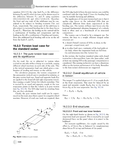
The torque T is applied about axis O O as couple R FT S F
thus causing a couple Tabout the vehicle centreline. This at the front suspension. This must be balanced by an
is reacted by an equal and opposite couple at the rear equal and opposite couple R RT S R due to the reaction
suspension points so that the vehicle is in pure torsion forces R RT at the rear suspension. See Fig. 16.2-8:
(see Fig. 16.2-8). The SSS edge loads Q, resulting from
this, are then calculated. T ¼ R FT S F ¼ R RT S R
Clearly, the pure torsion load could not be experi-
enced on the road, since there cannot be a negative wheel Hence
reaction. However, if road case loads are required, then R FT ¼ T=S F R RT ¼ R FT S F =S R ¼ T=S R
T
16.2.3.3 End structures
S R
R RT
16.2.3.3.1 Front and rear inner fenders
O
R RT On the right-hand fender as shown in Fig. 16.2-9, the
suspension load acts upward. This is reacted by an equal
downward force on the panel where it is joined to the
bulkhead.
For moment equilibrium, the couple caused by the
R FT
offset L 1 of forces R FT is balanced by complementary
O
S F R FT shear forces PFT at top and bottom of the panel:
Front
T
R FT L 1 ¼ P FT h 1 thus
P FT ¼ R FT L 1 =h 1 ¼ TL 1 =ðS F h 1 Þ
Fig. 16.2-8 Vehicle in pure torsion.
548