Page 538 - Automotive Engineering Powertrain Chassis System and Vehicle Body
P. 538

Standard sedan (saloon) – baseline load paths    C HAPTER 16.2


                                                                  I 2       I l
                                    I pt       I 1
                                                      P 4       P 9
                                     F /2                                      F /2
                                                                                l
                                      pt
                                  front
                              h               (iii)    P 3       P 8       (vii)        rear  h 2
                               1
                                                       P 5     P 10
                                           R FL                           R RL
                                                                                   /2
                                                                                −F l
                                                      P   Shear      zero
                                       zero            3   force
                                  −F pt /2                        −P 8
                                (I + I )/2 + R I
                             −F pt pt   1  FL 1
                                                                          −F (I + I )/2 + R I
                                                                                2
                                                                                     RL 2
                                                                            l l
                                        zero                             zero
                                                         Bending
                                −F I /2                   moment                   −F I /2
                                  pt pt
                                                                                     l l
                             (a)      Front inner wing          (b)     Rear quarter panel
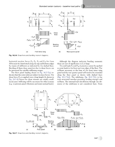
           Fig. 16.2-6 Shear force and bending moment diagrams.
           horizontal reaction forces P 4 ,P 5 ,P 9 and P 10 for these  Although the diagram indicates bending moments
           SSSs must be distributed along the top and bottom edges  these are not of significance as l 5 is large.
           by means of stiffeners as indicated by the dashed lines.  The end loads P 5 and P 10 in practice cannot be applied
           Buckling of these deep members due to shear forces can  as point loads to the front and rear edges of the floor. The
           be prevented by suitable stiffening swages.        stiffener necessary at the base of the front inner wing
             The floor panel loading shown in Fig. 16.2-7(a) in-  panel and the rear quarter panel will need to be extended
           dicates that the outer sides are subject to shear forces. The  along the floor panel as shown with dashed lines
           shear force P 13 is applied over a long length (l 5 shown in  (Fig. 16.2-7(a)). The sideframe, Fig. 16.2-7(b), is the
           Fig. 16.2-4) hence the shear stresses are usually small.  main structural member providing bending strength and
           Local panel stiffening will be necessary for other reasons  stiffness. The internal load distribution through the ele-
           (e.g. to prevent panel vibrations and resist normal loads).  ments of the sideframe is not considered here. From


                                       P 5  front  P 5

                                                                                    P 12
                                                                   P 7
                                  P 13     (xi)      P 13
                                                           P 6       P 1     P 2       P 11
                                                                                  (xii)
                                                                         P 13
                                      P 10        P 10      P 6
                                                                             zero
                                             P 5       Shear
                                   P 13   zero         force                          −P 11
                                                    −P 13     P I + P h     P (I − I ) + P h
                                                                    7 1
                                                               6 3
                                          −P 5                               11 5   4  12 2
                             P  (W−t )/2            Bending
                              13
                                   f
                                                    moment
                                                                                      P 12 h 2
                                                         P h
                                                          7 1
                                           zero                          zero
                             (a)         Floor panel       (b)         Sideframe
           Fig. 16.2-7 Shear force and bending moment diagrams.
                                                                                                      547
   533   534   535   536   537   538   539   540   541   542   543