
Page 534 - Automotive Engineering Powertrain Chassis System and Vehicle Body
P. 534
Standard sedan (saloon) – baseline load paths C HAPTER 16.2
3. and 4. Inner wing panels carrying the power-train
and supported by the front suspension. F pt F F
5. Dash panel–transverse panel between passengers pf pr F l
and engine compartment.
6. Front parcel shelf.
I pt I pf I
7. and 8. Rear quarter panels carrying luggage loads I
and supported by the rear suspension. pr
R F L R R
9. Panel behind the rear seats.
10. Rear parcel shelf. Fig. 16.2-3 Payload distribution.
11. Floor panel front passengers/seats F pf , the rear passengers/seats F pr ,
12. and 13. Left-hand and right-hand sideframes. and the luggage F [ only are considered. The magnitude of
the loads is the weight of the component factored by
14. Windscreen frame.
a dynamic load factor. It should be noted that all these
15. Roof panel. loads are applied in the planes of SSSs. It is essential this
16. Backlight (rear window) frame. condition is achieved in order to ensure sufficient strength
and stiffness can be provided through the structure. The
These SSSs will be shown to be sufficient to carry the bending and shear loads on each component can be de-
two fundamental load cases of bending and torsion. Some termined and from these satisfactory stress levels can be
additional SSSs will be necessary for other load cases as determined.
described in section 16.2.4. Alternative SSSs may be
necessary when modelling particular vehicles. The vehi-
cle engineer must use his knowledge and make his/her 16.2.2.2 Payload distribution
own subjective assessment for the model that best rep-
resents a particular structure. The passenger car structure when viewed in side elevation
(Fig. 16.2-3) can be considered as a simply supported
beam, the supports are at the front and rear axles. First,
16.2.2 Bending load case for the masses of these components and their longitudinal and
the standard sedan (saloon) lateral positions in the vehicle must be known, then the
front and rear suspension reaction forces can be obtained.
Referring to Fig. 16.2-3, by taking moments about the
16.2.2.1 Significance of the bending load
rear suspension mounting the front suspension reaction is:
case
F pt ðL þ l pt Þþ F ðL l Þþ F pr ðL l pr Þ F l
pf
l l
pf
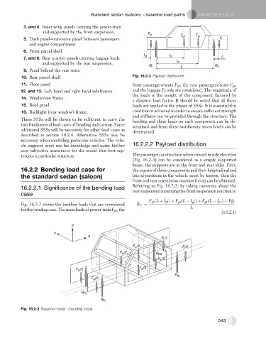
Fig. 16.2-2 shows the baseline loads that are considered R F ¼ L
forthebendingcase.Themainloadsofpower-trainF pt ,the
(16.2.1)
Z
Y
X
F /2
F pr /2 F /2
F /2 R RR
pf
F /2
pr
F pt /2 F /2
pf
R RL
F pt /2
R FR
R FL
Fig. 16.2-2 Baseline model – bending loads.
543