
Page 533 - Automotive Engineering Powertrain Chassis System and Vehicle Body
P. 533
16.2 Chapter 16.2
Standard sedan
(saloon) – baseline load paths
Jason Brown, A.J. Robertson and Stan Serpento
the lower rails (e.g. for engine mounting) and the upper
OBJECTIVES
flanges. To keep the model simple, the suspension tower
To demonstrate that a car structure can be repre- loads are fed directly into the webs of the cantilevers.
sented by simple structural surfaces (SSSs). Where it is necessary to carry out-of-plane loads,
To introduce the load paths in a sedan structure for ‘supplementary SSSs’ (acting as beams) are provided, for
different load cases. example as floor cross-members and parcel shelves. To
reduce complexity in the standard sedan, the parcel
shelves are not considered to be part of the surface of the
16.2.1 Introduction
passenger compartment ‘torsion box’ for the torsion load
case. Both parcel trays are, however, necessary for car-
The structures of different sedan passenger car structures rying loads in the bending load case, and for carrying
vary according to size, vehicle layout (‘package’) and type loads into the ‘torsion box’ in the torsion case.
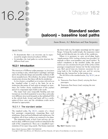
and to the particular design and assembly methods of dif- The 16 SSSs in the standard sedan, Fig. 16.2-1, are as
ferent manufacturers. Nevertheless, the nature of integral follows:
construction dictates that there will also be similarities.
In this chapter, a simplified car structure referred to as 1. Transverse floor beam (front) carrying the front
the ‘standard sedan’ is used as the basis for an in- passengers.
troductory discussion of load paths in integral car struc- 2. Transverse floor beam (rear) carrying the rear
tures. For further clarity, simplification of the payload passengers.
and of the suspension input loads is also made.
The major load cases (especially bending and pure
torsion) are described separately because they each make 16
Z 13 8
very different structural demands on the individual SSSs Y 15 10 12
in the vehicle body. Actual road loads will be a combi- X 7
nation of these cases, and the calculation results can be 14
obtained as appropriate.
6
16.2.1.1 The standard sedan
The standard sedan, Fig. 16.2-1, consists of a ‘closed
box’ passenger compartment, comprising floor, roof,
sideframes, front and rear bulkheads and windscreen. For
simplicity, all of these surfaces are assumed to be plane. 2 9
The suspension loads, at both front and rear, are car- 4 5 1 11
ried on deep, stiff boom/panel cantilevers attached to the 3
ends of the compartment. These are a simplified repre-
sentation of the inner wing panels. The booms represent Fig. 16.2-1 Baseline model.
Motor Vehicle Structures; ISBN: 9780750651349
Copyright Ó 2001 Jason Brown, A.J. Robertson and Stan Serpento. All rights of reproduction, in any form, reserved.