
Page 537 - Automotive Engineering Powertrain Chassis System and Vehicle Body
P. 537
CHAP TER 1 6. 2 Standard sedan (saloon) – baseline load paths
In practice some rounding errors due to difficulties in this manner. These panels are relatively deep so bending
defining the exact positions of each force may occur. stresses and deflections will be small although stiffening
It should now be noted that windscreen frame (14), at the top and bottom edges will be necessary to prevent
roof panel (15), and backlight (16) SSSs are not subject buckling. The outer sections carrying the shear force will
to any load for this bending case. probably require swaging to prevent shear buckling.
The loading conditions on the front and rear parcel
shelves are once again similar. The front shelf shown in
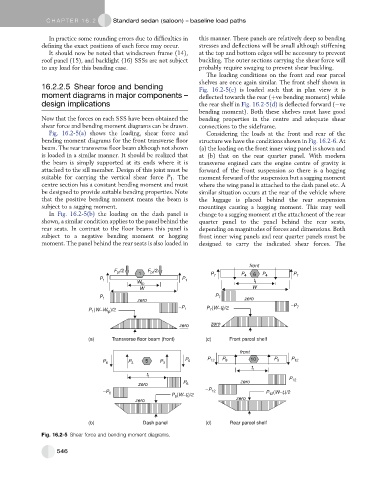
16.2.2.5 Shear force and bending Fig. 16.2-5(c) is loaded such that in plan view it is
moment diagrams in major components – deflected towards the rear (þve bending moment) while
design implications the rear shelf in Fig. 16.2-5(d) is deflected forward ( ve
bending moment). Both these shelves must have good
Now that the forces on each SSS have been obtained the bending properties in the centre and adequate shear
shear force and bending moment diagrams can be drawn. connections to the sideframe.
Fig. 16.2-5(a) shows the loading, shear force and Considering the loads at the front and rear of the
bending moment diagrams for the front transverse floor structure we have the conditions shown in Fig. 16.2-6.At
beam. The rear transverse floor beam although not shown (a) the loading on the front inner wing panel is shown and
is loaded in a similar manner. It should be realized that at (b) that on the rear quarter panel. With modern
the beam is simply supported at its ends where it is transverse engined cars the engine centre of gravity is
attached to the sill member. Design of this joint must be forward of the front suspension so there is a hogging
suitable for carrying the vertical shear force P 1 . The moment forward of the suspension but a sagging moment
centre section has a constant bending moment and must where the wing panel is attached to the dash panel etc. A
be designed to provide suitable bending properties. Note similar situation occurs at the rear of the vehicle where
that the positive bending moment means the beam is the luggage is placed behind the rear suspension
subject to a sagging moment. mountings causing a hogging moment. This may well
In Fig. 16.2-5(b) the loading on the dash panel is change to a sagging moment at the attachment of the rear
shown, a similar condition applies to the panel behind the quarter panel to the panel behind the rear seats,
rear seats. In contrast to the floor beams this panel is depending on magnitudes of forces and dimensions. Both
subject to a negative bending moment or hogging front inner wing panels and rear quarter panels must be
moment. The panel behind the rear seats is also loaded in designed to carry the indicated shear forces. The
front
F /2 1 F /2 P P 6 P
pf
pf
P 1 P 1 7 4 t P 4 7
W fp f
W W
P 1 P 7 zero
zero
−P P (W−t f )/2 −P 7
(W−W )/2 1 7
P 1 fp
zero zero
(a) Transverse floor beam (front) (c) Front parcel shelf
front
P 6 P 3 5 P 3 P 6 P 12 P 9 10 P 9 P 12
t r
t f P
P zero 12
zero 6
−P 6 −P 12 P 12 (W−t )/2
r
P 6 (W−t )/2
f
zero zero
(b) Dash panel (d) Rear parcel shelf
Fig. 16.2-5 Shear force and bending moment diagrams.
546