Page 535 - Automotive Engineering Powertrain Chassis System and Vehicle Body
P. 535

CHAP TER 1 6. 2       Standard sedan (saloon) – baseline load paths

               where l pt ,l pf ,l pr and l l are defined in Fig. 16.2-3.  When beginning the bending analysis it is essential to
                 Similarly, taking moments about the front suspension  start at the central floor area. In this simple model it is
               mounting:                                          assumed that the passenger loads are carried by the two
                                                                  transverse floor beams SSS (1) and (2). These floor
                                                                  beams are supported at each end by the side-frame forces
                      F l þ F pr l pr þ F ðL þ l Þ  F pt l pt
                       pf pf
                                           l
                                      l
                 R R ¼                                 (16.2.2)   P 1 and P 2 . Note that there is an equal but opposite force
                                    L
                                                                  acting on the sideframe.
                                                                    Consider now the inner front wings SSS (3) and (4),
                 Check the answers by verifying R R þ R F ¼ F pt þ
               F pf  þ F pr þ F :                                 the loads acting on these are the loads from the power-
                            l
                 When investigating a particular vehicle many more  train P t /2 and from the front suspension R FL . The applied
               components can be considered making a more accurate  loads F pt /2 and R FL are held in equilibrium by the
               model. Typical items that may be included are: front  end loads P 4 and P 5 and by the edge (shear) load P 3 . The
               bumper, radiator, battery, instrument panel/steering  shear load P 3 reacts into the dash panel while the end
               column, exhaust, fuel tank, spare wheel, rear bumper and  load P 4 reacts into the front parcel shelf (6), and P 5 into
               distributed loads due to the weight of the body structure.  the floor panel (11). These forces can be obtained by the
               If these are to be included, the positions of all these  equations of statics, i.e. resolving forces and taking
               components as well as their masses must be known. The  moments.
               suspension reactions can be calculated with a similar  When building the SSS model representing the
               procedure.                                         vehicle it must always be remembered that the forces
                                                                  must act in the plane of an SSS. Failure to provide
                                                                  sufficient SSSs to satisfy this requirement soon reveals
               16.2.2.3 Free body diagrams                        a weakness or unsatisfactory load path in the structure.
               for the SSSs                                       Note, the horizontal SSS (6) is necessary in order to
                                                                  carry force P 4 .
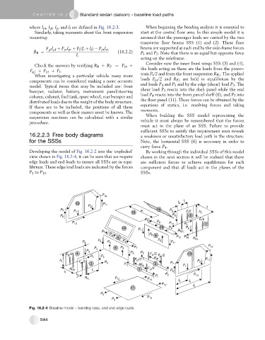
               Developing the model of Fig. 16.2-2 into the ‘exploded’  By working through the individual SSSs of this model
               view shown in Fig. 16.2-4, it can be seen that we require  shown in the next section it will be realized that there
               edge loads and end loads to ensure all SSSs are in equi-  are sufficient forces to achieve equilibrium for each
               librium. These edge/end loads are indicated by the forces  component and that all loads act in the planes of the
               P 1 to P 13 .                                      SSSs.


                                                P 12
                                                                                      I l
                                    13           P 11                              I 2
                                          P 2
                                                                                                t r
                             P 7                                  w       16   P 9     F l /2
                                   P 1
                                                              15                             h 2
                                                                                 P 8     8
                             P 6
                                                                                             F l /2
                                                                    P 12
                                                                         P 9
                                  P 13                                         P 10
                                                                                      P 9       7
                                                         14      P 11      10  P 9     P 8
                                                                                   R RR
                                                P 7
                                                    P 4               P 8 9
                                                       6                          P 12 P 10  R RL
                                              P 6         P 4             P 8
                                       P 4         P 3                          P 11
                                                                                                 P 12
                                                      5  P 3   P 7
                                            P 4
                                         P 3
                               F pt /2  4                    P 6  P 2  F pr /2  F pr /2  12
                                           P 5  P 3
                                                               F pf /2  w rp                    P 11
                             h 1
                                     F pt /2                                                P 2
                                           3     P 5      P 1           2       P 7
                                                                 W fp
                                                                                     P 1
                                 R FR      I 1                   1   F pf /2
                                                                                P 6
                               t f
                                    I pt                                     P 2          P 13
                                                                         P 1
                                        R FL          P 13           P 10
                                                                                   I 3
                                                                                        I 4
                                                                            P 10
                                                                                          I 5
                                                              11
                                               P 5
                                                                     P 13
                                                     P 5
               Fig. 16.2-4 Baseline model – bending case, end and edge loads.
                    544
   530   531   532   533   534   535   536   537   538   539   540