
Page 531 - Automotive Engineering Powertrain Chassis System and Vehicle Body
P. 531
CHAP TER 1 6. 1 Terminology and overview of vehicle structure types
Fig. 16.1-23 Modern integral body-in-white (courtesy General Motors Corporation).
mentioned that spring rates for axle and engine suspen- varying thickness) are also used widely, in addition to steel
sions, and for the suspension bushes had to be reduced sandwich panels. Laser welding and adhesive bonding,
due to increased ‘harshness’ (the passing of transient both of which are stiffer than spot welding, are used
forces to the vehicle occupants) in the integral vehicle. extensively to join the panels together. The result is a
Fig. 16.1-23 shows a modern example of an integral structure which was recorded to be lighter and stiffer
‘body-in-white’ (i.e. bare body shell). The integral body is thanthe‘traditional’integralsteelbodiesitwascomparedto.
really a mixture of the monocoque and the ‘birdcage’ Although, at the time of writing, steel is used almost
types. The body forms a ‘closed box’ torsion structure universally for high volume mass produced car bodies,
(with consequent high stiffness). The walls, or ‘surfaces’ the suppliers of competing materials, such as aluminium
of the box, consist of the skin panels (such as the roof, and composite plastics, have been developing integral
floor, bulkheads, etc.) where possible. Elsewhere open body technologies also. For example, the aluminium in-
bay ring frames (sideframe, windshield frames, etc.) tensive vehicle, AIV, is made of pressed sheet aluminium
form the surface of the box, wherever openings are panels, ‘weld-bonded’ together. In their 1989 book,
required. Beam members are also used to carry out- Nardini and Seeds have discussed the design issues for
of-plane loads, for example in the floor. aluminium integral bodies.
In the integral structure the panels and body compo-
nents are stamped from sheet steel and fixed together
mostly by spot welding, although clinching, laser welding
or other methods are sometimes used for particular lo-
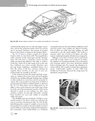
cations. The beam members are formed out of folded or
pressed sheet steel shapes, welded together as shown in
Fig. 16.1-24. These beams can be independent (e.g. B-
pillar), or they can be formed as part of the larger panels
(as in the case of the transmission tunnel), or they can be
attached to panels by spot welding (e.g. floor cross-
members, rockers). To avoid ugly ‘sink marks’, attached
beam members are never spot welded to externally
visible skin panels.
The ultralight steel auto steel body, ULSAB is a mod-
ernized version of this theme which may well show the
way to near-future developments (Fig. 16.1-25). In this,
hydroforming (the creation of complex cross-sections by
forcing tubes into moulds by internal hydraulic pressure)
is used widely as an alternative method of forming beam- Fig. 16.1-24 Integral body floor assembly, showing structural
like components. ‘Laser welded blanks’ (i.e. of tailored members.
540