
Page 540 - Automotive Engineering Powertrain Chassis System and Vehicle Body
P. 540
Standard sedan (saloon) – baseline load paths C HAPTER 16.2
16.2.3.3.2 Dash
P FT
Torque T is applied to the engine bulkhead by the re-
actions R FT from the fender webs acting at a separation
S F giving a couple P FT S F ¼ T as shown in Fig. 16.2-10.
P FT
The reactions P FT to the fender upper flange forces are
carried by the parcel shelf which must be stiff in the
R FT
R FT
appropriate direction. The reactions to the engine rail
T
forces P FT pass to the floor as in-plane forces in the di-
h 1 R FT
rections shown in Fig. 16.2-12.
R FT
The rear fender forces are reacted in an identical way.
P FT S F
Owing to the directions of the suspension forces in the
P FT
torsion case, forces P RT apply a couple to the parcel
L 1
shelves of P RT S R . This is also the case for the floor.
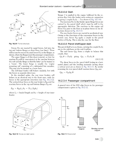
Fig. 16.2-9 Frontal structure. 16.2.3.3.3 Parcel shelf/upper dash
Forces P FT are reacted by equal forces, fed into the The parcel shelf acts as a beam, carrying the couple P FT S F
top and bottom flanges as shear flows (see later). These out to the sideframe at the mid A-pillars.
will in turn be reacted by axial forces P FT in the flanges, as The end forces Q X1 form a couple to balance this
shown, where the flanges meet the passenger compartment. couple, thus:
The upper flange is of thin sheet material, so that the Q X1 B ¼ P FT S F giving Q X1 ¼ P FT S F =B
reaction P FT will be concentrated at the junction between (16.2.19)
the web and the flange so that the latter can be treated as The shear forces in the parcel shelf (acting in a hori-
a ‘boom’. The lower flange is usually the ‘engine zontal plane) and the bending moments (acting about
mounting rail’ consisting of a substantial box member. a vertical axis) are as shown in Fig. 16.2-11. By similar
This may also be treated as a boom here. reasoning the rear parcel shelf reaction forces Q X2 are:
The left-hand fender will behave similarly, but with
the forces in opposite directions. Q X2 ¼ P RT S R =B
In the standard sedan, the rear inner fenders will
behave in an identical way to the front ones, with the
forces in the appropriate directions (see Fig. 16.2-12). 16.2.3.4 Passenger compartment
The vertical shear force on the rear fender is R RT and the
reaction forces in the top and bottom flanges P RT are:
A general view of the SSS edge forces in the passenger
compartment is given in Fig. 16.2-12.
P RT ¼ R RT L 2 =h 2 ¼ TL 2 =ðS R h 2 Þ
where L 2 ¼ loaded length and h 2 ¼ height of rear inner
fender.
Q x1
P FT
P FT
P
P FT FT
T
R FT
R FT
P FT Q x1 Shear force
diagram Bending moment
P FT diagram
Fig. 16.2-10 Forces on dash panel. Fig. 16.2-11 Parcel shelf.
549