
Page 542 - Automotive Engineering Powertrain Chassis System and Vehicle Body
P. 542
Standard sedan (saloon) – baseline load paths C HAPTER 16.2
Thus for moment equilibrium: L 7
T ¼ Q 1 h 2 þ Q 6 B (16.2.25) Q 4
As before Q 1 TOP and Q 1 BOTTOM are equal and Q 3 r Q 5
opposite, as are Q 2 LEFT and Q 2 RIGHT. Because of the r 3 4 r 5 Q X2
externally applied torque T, the edge forces Q 1 ,Q 6 do Q X1 G H
not form opposing couples (although overall the panel h Q 2 r 2 r 6
1 h 2
must be in moment equilibrium). As on all such surfaces r 7 Q 6 Z
with additional external forces or moments, force Q 1 is
the net force on the top of this panel. The rear seat X Q 7
bulkhead is sometimes a continuous panel, or it may L 5
consist of a truss structure, formed by punching
triangular holes leaving diagonal members forming a Fig. 16.2-14 Sideframe.
‘triangulated truss’ SSS (Fig. 16.2-13).
vehicle experience identical edge loads, but in opposite
16.2.3.4.6 Floor directions. Force and moment equilibrium will be
obeyed. Clearly, the sideframes are crucial in ‘gathering’
This receives equal and opposite edge forces Q 1 from the
front and rear bulkheads and Q 7 at the sides, from the the edge forces from the other surfaces.
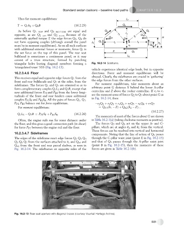
sideframes. The forces Q 1 and Q 7 are oriented so as to For moment equilibrium, take moments about an
form complementary couples Q 1 L 5 and Q 7 B, except that arbitrary point G distance X behind the lower A-pillar
now additional forces P FT and P RT from the lower longi- centreline and Z above the rocker centreline. If r 2 to r 7
tudinals of the front and rear fenders cause additional are the moment arms of forces Q 2 to Q 7 about point G as
couples P FT S F and P RT S R . All the pairs of forces Q 1 ,Q 7 , in Fig. 16.2-14, then:
P FT , P RT balance out for force equilibrium. r 2 Q 2 þ r 3 Q 3 þ r Q þ r 5 Q 5 r 6 Q 6 þ r 7 Q 7
4
4
For moment equilibrium: ¼ Q X1 ðh 1 ZÞþ Q X2 ðh 2 ZÞ.
(16.2.27)
Q 1 L 5 Q 7 B ¼ P FT S F þ P RT S R (16.2.26)
The moments of most of the forces about G are shown
Often, the engine rails run for some distance under in Table 16.2-1(a) (taking clockwise moments as positive).
the floor, and this gives a good connection path (in shear) The forces Q 3 and Q 5 act on the upper A- and C-
for force P FT between the engine rail and the floor. pillars, which are at angles q A and q C from the vertical.
These forces can be resolved into vertical and horizontal
16.2.3.4.7 Sideframes components. Noting that the line of action of Q 5 passes
through the C-pillar waist joint (point E in Fig. 16.2-15)
The edges of the sideframe react edge forces Q 2 Q 3 Q 4
Q 5 Q 6 Q 7 from the surfaces attached to it, and Q x1 and and that of Q 3 passes through the A-pillar waist joint
Q x2 from the front and rear parcel shelves, as seen in (point B in Fig. 16.2-15), then the moments of these
Fig. 16.2-14. The sideframes on opposite sides of the forces are given in Table 16.2-1(b).
Fig. 16.2-13 Rear seat aperture with diagonal braces (courtesy Vauxhall Heritage Archive).
551