Page 541 - Automotive Engineering Powertrain Chassis System and Vehicle Body
P. 541

CHAP TER 1 6. 2       Standard sedan (saloon) – baseline load paths


                                 Q 3
                                        Q X1       L 7        h 4
                                                                                          R
                                                                           Q 1              RT
                                 Q 2                 Q 4          Q 1  Q 5
                                          h 3                                                   R RT
                                              Q 3    Q 1                P        Q 5
                                                                   Q 4   RT   Q 1
                                                                           Q X2
                                                                 Q 4                   Q1
                                           Q X1             Q                 Q 6
                                                     Q       3             Q        T
                                  h 1              P  1                      5
                                       Q 2   Q 1    FT  P FT  Q 3  Q X1  Q X2  Q 6        Q 6  h
                                          R FT                                       Q 1       2
                                     P FT     T  R FT   Q X1          Q             B
                                                           Q 2         7         S R
                                       R FT  Q 1     Q        Q            Q
                              R FT        P FT         2       7            1
                                               P FT                 P RT
                                              R FT               P FT  P RT
                                    R FT       P FT                  P FT
                                                            Q 1           Q 7
                                                                                 L
                                                       S F                        5

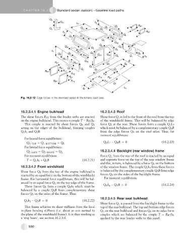
               Fig. 16.2-12 Edge forces in the standard sedan in the torsion load case.


               16.2.3.4.1 Engine bulkhead                         16.2.3.4.3 Roof
               The shear forces R FT from the fender webs are reacted  Shear force Q 1 is fed to the front of the roof from the top
               on the engine bulkhead. This creates a couple T ¼ R FT S F .  of the windshield frame. This will be balanced by edge
                 This couple is reacted by shear forces Q 1 and Q 2  force Q 1 at the rear. These forces form a couple Q 1 L 7
               acting on the edges of the bulkhead, forming couples  which must be balanced by a complementary couple Q 4 B
               Q 1 h 1 and Q 2 B.                                 from the edge forces Q 4 on the roof sides. Thus, for
                                                                  moment equilibrium:
                 For lateral force equilibrium:
                                                                    Q 1 L 7   Q B ¼ 0                     (16.2.23)
                  Q 1 TOP ¼ Q 1 BOTTOM ¼ Q 1                                 4
                 For lateral force equilibrium:
                                                                  16.2.3.4.4 Backlight (rear window) frame
                  Q 2 LEFT ¼ Q 2 RIGHT ¼ Q 2
                 For moment equilibrium:                          Force Q 1 from the rear of the roof is reacted by an equal
                  T ¼ Q 1 h 1 þ Q 2 B                 (16.2.21)   and opposite force on the top of the rear window frame
                                                                  and this, in turn, is balanced by a force Q 1 on the bottom
               16.2.3.4.2 Front windshield                        of the window frame. The couple Q 1 h 4 from these forces
               Shear force Q 1 from the top of the engine bulkhead is  is balanced by the complementary couple Q 5 B from edge
               reacted by an equal force on the bottom of the windshield  forces Q 5 on the sides of the backlight frame.
               frame. For horizontal force equilibrium, this will be bal-  For moment equilibrium:
               anced by an equal force Q 1 on the top edge of the frame.
                                                                        4
                 These forces Q 1 form a couple Q 1 h 3 which must be  Q 1 h   Q 5 B ¼ 0                  (16.2.24)
               balanced by a couple Q 3 B from complementary shear
               forces Q 3 on the sides of the frame. Thus
                                                                  16.2.3.4.5 Rear seat bulkhead
                 Q 1 h 3   Q 3 B ¼ 0                  (16.2.22)
                                                                  Shear force Q 1 is passed from the backlight frame to the
                 This frame achieves its shear stiffness from the local  top of the rear bulkhead. The top and bottom edge forces
               in-plane bending stiffness (i.e. about an axis normal to  Q 1 on the rear bulkhead and forces Q 6 on its sides form
               the plane of the windshield frame). It is thus working as  couples which are balanced by the couple T ¼ R RT S R
               a ‘ring beam’, see section 16.2.3.6.               applied by the rear fender webs to this panel.


                    550
   536   537   538   539   540   541   542   543   544   545   546