
Page 545 - Automotive Engineering Powertrain Chassis System and Vehicle Body
P. 545
CHAP TER 1 6. 2 Standard sedan (saloon) – baseline load paths
forces only (windshield, roof, backlight in this case) the more of Q X1 etc., to be conveyed downward to the
complementary shear flows q 3 q 4 q 5 will be equal to underbody (so-called ‘semi-open’ structure).
this, and hence equal to each other. The shear flow If the windshield glass is adhesive bonded to the
around this part of the sideframe is thus constant. This frame, then the glass will act as a substantial load path (as
reflects the Bredt–Batho theorem for shear flows in a shear panel). This will relieve the corner bending
closed sections subject to torsion, because the passenger moments on the frame (somewhat) and will make a sig-
compartment can be thought of as a closed tube running nificant increase in the shear stiffness of the window
across the car between the sideframes. For some of the frame. Cars with bonded screens have shown large tor-
other panels, such as bulkheads and floor, the edge sion stiffness increases (up to 60%). Care must be taken,
forces calculated above are affected by additional ex- however, to ensure that the load in the glass does not
ternal moments on the panel (e.g. R TF S F on the front cause it to break in extreme load cases (e.g. vehicle
bulkhead). This masks the complementary shear flow corner bump case, or wheel jacking for puncture). The
effect in these cases. For example, the couple vehicle stiffness and member stresses (e.g. corner
T ¼ R FT S F is introduced into the front bulkhead by bending moment in window frame) should not degrade
forces R FT (see Fig. 16.2-12) so that the shear force to unacceptable values in the event of a smashed
(and hence the local shear flow along the top and windshield.
bottom edges) varies across the panel. Thus, force Q 1 is Windshields attached with (elastomer) gaskets give
the net force on the top and bottom of this bulkhead. a much less significant contribution to the structure, due
The equality of complementary shear flows can also be to the flexibility of the gasket.
used as a check on the solutions for the forces Q on the (c) The sideframe consists of two (or sometimes
structural surfaces that have edge forces only (e.g. roof, three) rings, bordered by the A-, B- and C- (etc.) pillars.
windshield). Again, this check cannot be applied directly The share of the shear load Q 4 carried by each of these
to structural surfaces (e.g. floor) which are subject to beams will be in proportion to their relative stiffness and
extra forces in addition to the edge forces. hence will depend on their second moments of area, and
(b) The ‘shear panel’ load path in the compartment lengths (see Fig. 16.2-17).
depends on all SSSs in it carrying shear effectively. Calculating the share of the load in each pillar and
The least effective SSSs in this respect are the ring hence the bending moments and the stresses in the ring
frames, including the sideframes and the windshield frames accurately is complicated, particularly in the
frame. This type of structural surface achieves its in- multiple ring case (sideframe), since they are statically
plane shear stiffness by acting as a ring beam, with local indeterminate (three redundancies per 2D ring).
bending of its edge beams about an axis normal to the The sideframe is subject to overall shear, and since it is
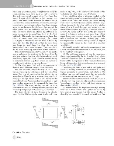
plane of the frame. As discussed earlier, this leads to high a (multi-bay) ring beam, its edge members experience
local bending moments at the corners of the frame (see ‘contraflexure bending’, giving high joint stresses as
Fig. 16.2-16). The edge members are said to be in shown in Fig. 16.2-17.
‘contraflexure’ since the bending moment (and hence the (d) As noted above, the ring frames have high bending
curvature) changes sign part-way along the member. moments at their corners. Some pillars are shared by
The least effective of these frames is the slender two adjacent ring frames (e.g. the upper A-pillar is
upper A-pillar. Thickening the lower A-pillar will cause shared by the windshield surround and sideframe. See
Q 1
Q 1
Q 5 Q
Q 5 5
BM
Q 1 Q 1
Fig. 16.2-16 Ring beam.
554