Page 550 - Automotive Engineering Powertrain Chassis System and Vehicle Body
P. 550

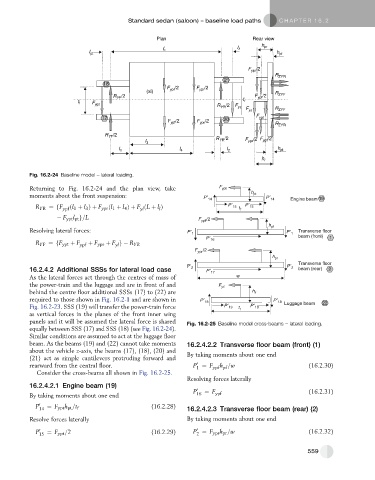
Standard sedan (saloon) – baseline load paths    C HAPTER 16.2


                                                    Plan                           Rear view
                                                                                      h
                                                      L                       I        pr
                              I pt                                                         h pf

                                                                                  F ypr /2
                                                                                           R ZYR
                                                                          21
                                   18
                                                       F ypf /2  F ypr /2
                                                 (xi)
                                      R /2                                          F ypf /2  R ZYF
                                       YF
                          t f                                                   t r
                                                                        R  /2  F
                               F ypt
                                                                               y
                                                                         YR
                                                                                 F y       R ZYF
                                  17                                      20         F ypt
                                                        F ypf /2  F ypr /2                 R ZYR
                                      /2
                                   R YF
                                                                       R YR /2          /2
                                                I 3                              F ypr /2 F ypf
                                        I 1                 I 4            I 2              h pt
                                                                                      h l
           Fig. 16.2-24 Baseline model – lateral loading.
           Returning to Fig. 16.2-24 and the plan view, take
           moments about the front suspension:

             R YR ¼fF ypf ðl 1 þ l 3 Þþ F ypr ðl 1 þ l Þþ F ðL þ l Þ
                                          4
                                                     l
                                               yl
                      F ypt l pt g=L
           Resolving lateral forces:
             R YF ¼fF ypt þ F ypf  þ F ypr þ F g  R YR
                                       yl


           16.2.4.2 Additional SSSs for lateral load case
           As the lateral forces act through the centres of mass of
           the power-train and the luggage and are in front of and
           behind the centre floor additional SSSs (17) to (22) are
           required to those shown in Fig. 16.2-1 and are shown in
           Fig. 16.2-23. SSS (19) will transfer the power-train force
           as vertical forces in the planes of the front inner wing
           panels and it will be assumed the lateral force is shared  Fig. 16.2-25 Baseline model cross-beams – lateral loading.
           equally between SSS (17) and SSS (18) (see Fig. 16.2-24).
           Similar conditions are assumed to act at the luggage floor
           beam. As the beams (19) and (22) cannot take moments  16.2.4.2.2 Transverse floor beam (front) (1)
           about the vehicle z-axis, the beams (17), (18), (20) and  By taking moments about one end
           (21) act as simple cantilevers protruding forward and
                                                                 0
           rearward from the central floor.                      P ¼ F  ypf pf                         (16.2.30)
                                                                         h =w
                                                                 1
             Consider the cross-beams all shown in Fig. 16.2-25.
                                                              Resolving forces laterally
           16.2.4.2.1 Engine beam (19)
                                                                P 0  ¼ F                              (16.2.31)
           By taking moments about one end                       16    ypf
             P 0  ¼ F ypt h pt =t                 (16.2.28)
              14          f                                   16.2.4.2.3 Transverse floor beam (rear) (2)
           Resolve forces laterally                           By taking moments about one end
                                                                 0
             P 0 15  ¼ F ypt =2                   (16.2.29)     P ¼ F ypr h pr =w                     (16.2.32)
                                                                 2

                                                                                                     559
   545   546   547   548   549   550   551   552   553   554   555