
Page 548 - Automotive Engineering Powertrain Chassis System and Vehicle Body
P. 548
Standard sedan (saloon) – baseline load paths C HAPTER 16.2
Fig. 16.2-20 Torsion stiffening by ‘boxing in’ localized regions of
body. Frontal Front Compartment Rear Rear
structure dash b′head structure
will provide some torsion stiffness. The sideframes,
K 1 K 2 K 3 K 4 K 5
acting as stiff levers, will make this torsion stiffness
available to the whole body. The added members making Fig. 16.2-22 Structures in series.
up the box may already be present, providing other
functions (e.g. instrument panel, floor cross-member,
etc.). Examples are shown in Fig. 16.2-20. 16.2.3.7.3 Effect of one poor subassembly on
This approach is likely to be less weight efficient, and overall torsion stiffness
more prone to high stress/strain problems (fatigue, For the torsion case, the vehicle behaves as a set of
corrosion) than the true ‘closed’ integral structure de- five subassemblies in series in torsion as shown in
scribed in section 16.2.3.4. Fig. 16.2-22: (1) frontal structure, (2) dash, (3) passen-
ger compartment, (4) rear bulkhead/hat shelf, (5) rear
16.2.3.7.2.3 Provision of true grillage structure in structure.
floor For structures in series, the overall torsion stiffness
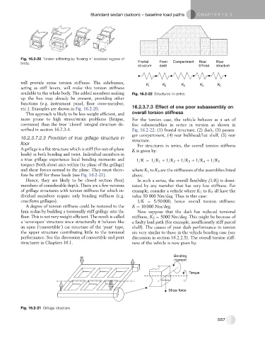
A grillage is a flat structure which is stiff (for out-of-plane K is given by:
loads) in both bending and twist. Individual members in
a true grillage experience local bending moments and 1=K ¼ 1=K 1 þ 1=K 2 þ 1=K 3 þ 1=K þ 1=K 5
4
torques (both about axes within the plane of the grillage)
and shear forces normal to the plane. They must there- where K 1 to K 5 are the stiffnesses of the assemblies listed
fore be stiff for these loads (see Fig. 16.2-21). above.
Hence, they are likely to be closed section (box) In such a series, the overall flexibility (1/K) is domi-
members of considerable depth. There are a few versions nated by any member that has very low stiffness. For
of grillage structures with torsion stiffness for which in- example, consider a vehicle where K 1 to K 5 all have the
dividual members require only bending stiffness (e.g. value 50 000 Nm/deg. Thus in this case:
cruciform grillages). 1/K ¼ 5/50 000, hence overall torsion stiffness:
A degree of torsion stiffness could be restored to the K ¼ 10 000 Nm/deg.
faux sedan by building a torsionally stiff grillage into the Now suppose that the dash has reduced torsional
floor. This is not very weight efficient. The result is called stiffness, K 2 ¼ 5000 Nm/deg. This might be because of
a ‘semi-open’ structure since structurally it behaves like a faulty load path (for example, insufficiently stiff parcel
an open (‘convertible’) car structure of the ‘punt’ type, shelf). The causes of poor dash performance in torsion
the upper structure contributing little to the torsional are very similar to those in the vehicle bending case (see
performance. See the discussion of convertible and punt discussion in section 16.2.2.5). The overall torsion stiff-
structures in Chapters 16.1. ness of the vehicle is now given by:
Bending
moment
Torque
Shear force
Fig. 16.2-21 Grillage structure.
557