Page 554 - Automotive Engineering Powertrain Chassis System and Vehicle Body
P. 554

Standard sedan (saloon) – baseline load paths    C HAPTER 16.2


                                   Z
                                                                   R ZXR /2
                            Y
                                          X                                 /2
                                                                          F x
                                                             F xpr /2
                                                                                  F /2
                                                                                   x
                                                         /2
                                                       F xpf
                                                                       F xpr /2
                                                              R XR /2
                                         R ZXF /2
                                                                                 R ZYR /2
                                      /2                       F  /2
                                   F xpt                        xpf
                                           F xpt /2
                                                                           R XR /2
                                                 R ZXF /2
                                    R /2
                                     XF
                                             /2
                                          R XF
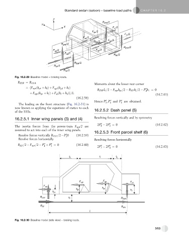
           Fig. 16.2-29 Baseline model – braking loads.
             R ZXF ¼ R ZXR
                                                              Moments about the lower rear corner
                  ¼fF xpt ðh pt þ h Þþ F xpf ðh þ h Þ           R ZXF l 1 =2   F xpt h pt =2   R XF h =2   P h 1 ¼ 0
                                        pf
                                             f
                                                                                               00
                               f
                    þ F xpr ðh pr þ h Þþ F ðh þ h Þg=L                                   f     4      (16.2.61)
                                f
                                            f
                                        l
                                     xl
                                                  (16.2.58)
                                                                        00
                                                                     00
                                                                               00
                                                              Hence P ; P and P are obtained:
                                                                               5
                                                                     3
                                                                        4
             The loading on the front structure (Fig. 16.2-31)is
           now known so applying the equations of statics to each
           of the SSSs.                                       16.2.5.2 Dash panel (5)
           16.2.5.1 Inner wing panels (3) and (4)             Resolving forces vertically and by symmetry
                                                                        00
                                                                  00
                                                                2P   2P ¼ 0                           (16.2.62)
           The inertia forces from the power-train F xpt /2 are   6     3
           assumed to act into each of the inner wing panels.
                                                              16.2.5.3 Front parcel shelf (6)
                                            00
             Resolve forces vertically R ZXF =2 P 0  (16.2.59)
                                            3
             Resolve forces horizontally                      Resolving forces horizontally
                                  00
                             00
             R XF =2   F xpt =2   P þ P ¼ 0       (16.2.60)     2P   2P ¼ 0                           (16.2.63)
                                                                  00
                                                                        00
                                  5
                             4
                                                                        4
                                                                  7
                                              l 6                l 7        l 8
                                                    F xpf           F xpr            F x
                             F xpt
                                                  h pf             h pr              h
                                   h pt
                           R ZXF             h f                               R ZXR
                           R XF                                                R XR
                                                           L


           Fig. 16.2-30 Baseline model (side view) – braking loads.


                                                                                                     563
   549   550   551   552   553   554   555   556   557   558   559