
Page 567 - Automotive Engineering Powertrain Chassis System and Vehicle Body
P. 567
CHAP TER 1 7. 1 Vehicle safety
Steering
wheel
Steering
wheel pad
Enhancer
Squib
Padded lid
Dash Bag
Bag
Inflator
Screen
Gas
Casing
generant
Inflator
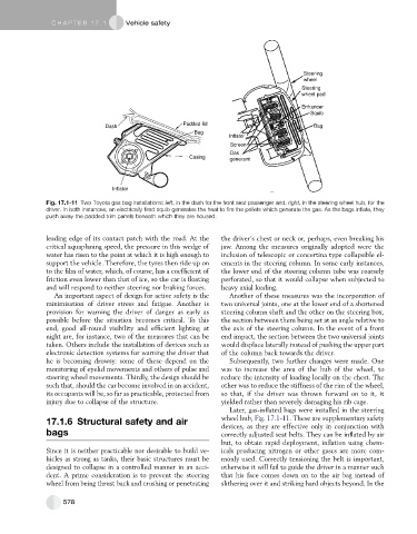
Fig. 17.1-11 Two Toyota gas bag installations: left, in the dash for the front seat passenger and, right, in the steering wheel hub, for the
driver. In both instances, an electrically fired squib generates the heat to fire the pellets which generate the gas. As the bags inflate, they
push away the padded trim panels beneath which they are housed.
leading edge of its contact patch with the road. At the the driver’s chest or neck or, perhaps, even breaking his
critical aquaplaning speed, the pressure in this wedge of jaw. Among the measures originally adopted were the
water has risen to the point at which it is high enough to inclusion of telescopic or concertina type collapsible el-
support the vehicle. Therefore, the tyres then ride up on ements in the steering column. In some early instances,
to the film of water, which, of course, has a coefficient of the lower end of the steering column tube was coarsely
friction even lower than that of ice, so the car is floating perforated, so that it would collapse when subjected to
and will respond to neither steering nor braking forces. heavy axial loading.
An important aspect of design for active safety is the Another of these measures was the incorporation of
minimisation of driver stress and fatigue. Another is two universal joints, one at the lower end of a shortened
provision for warning the driver of danger as early as steering column shaft and the other on the steering box,
possible before the situation becomes critical. To this the section between them being set at an angle relative to
end, good all-round visibility and efficient lighting at the axis of the steering column. In the event of a front
night are, for instance, two of the measures that can be end impact, the section between the two universal joints
taken. Others include the installation of devices such as would displace laterally instead of pushing the upper part
electronic detection systems for warning the driver that of the column back towards the driver.
he is becoming drowsy: some of these depend on the Subsequently, two further changes were made. One
monitoring of eyelid movements and others of pulse and was to increase the area of the hub of the wheel, to
steering wheel movements. Thirdly, the design should be reduce the intensity of loading locally on the chest. The
such that, should the car become involved in an accident, other was to reduce the stiffness of the rim of the wheel,
its occupants will be, so far as practicable, protected from so that, if the driver was thrown forward on to it, it
injury due to collapse of the structure. yielded rather than severely damaging his rib cage.
Later, gas-inflated bags were installed in the steering
wheel hub, Fig. 17.1-11. These are supplementary safety
17.1.6 Structural safety and air
devices, as they are effective only in conjunction with
bags correctly adjusted seat belts. They can be inflated by air
but, to obtain rapid deployment, inflation using chem-
Since it is neither practicable nor desirable to build ve- icals producing nitrogen or other gases are more com-
hicles as strong as tanks, their basic structures must be monly used. Correctly tensioning the belt is important,
designed to collapse in a controlled manner in an acci- otherwise it will fail to guide the driver in a manner such
dent. A prime consideration is to prevent the steering that his face comes down on to the air bag instead of
wheel from being thrust back and crushing or penetrating slithering over it and striking hard objects beyond. In the
578