
Page 569 - Automotive Engineering Powertrain Chassis System and Vehicle Body
P. 569
CHAP TER 1 7. 1 Vehicle safety
of the traditional thicker gauge high ductility material for
structural members and some body panels can help to
improve both crushability and integrity of structures.
It is important to design so that the loads due to an
Swages
impact (whether front, rear or side) are, so far as prac-
ticable, spread uniformly throughout the whole structure
and that the proportions of all the principal members of
the cage containing the occupants are adequate to react
those loads elastically. Diagonal and transverse members
may have to be incorporated under the floor and, possi-
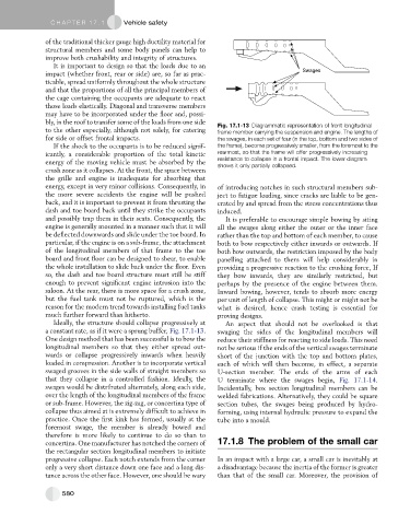
bly, in the roof to transfer some of the loads from one side Fig. 17.1-13 Diagrammatic representation of front longitudinal
to the other especially, although not solely, for catering frame member carrying the suspension and engine. The lengths of
for side or offset frontal impacts. the swages, in each set of four (in the top, bottom and two sides of
If the shock to the occupants is to be reduced signif- the frame), become progressively smaller, from the foremost to the
icantly, a considerable proportion of the total kinetic rearmost, so that the frame will offer progressively increasing
energy of the moving vehicle must be absorbed by the resistance to collapse in a frontal impact. The lower diagram
shows it only partially collapsed.
crush zone as it collapses. At the front, the space between
the grille and engine is inadequate for absorbing that
energy, except in very minor collisions. Consequently, in of introducing notches in such structural members sub-
the more severe accidents the engine will be pushed ject to fatigue loading, since cracks are liable to be gen-
back, and it is important to prevent it from thrusting the erated by and spread from the stress concentrations thus
dash and toe board back until they strike the occupants induced.
and possibly trap them in their seats. Consequently, the It is preferable to encourage simple bowing by siting
engine is generally mounted in a manner such that it will all the swages along either the outer or the inner face
be deflected downwards and slide under the toe board. In rather than the top and bottom of each member, to cause
particular, if the engine is on a sub-frame, the attachment both to bow respectively either inwards or outwards. If
of the longitudinal members of that frame to the toe both bow outwards, the restriction imposed by the body
board and front floor can be designed to shear, to enable panelling attached to them will help considerably in
the whole installation to slide back under the floor. Even providing a progressive reaction to the crushing force, If
so, the dash and toe board structure must still be stiff they bow inwards, they are similarly restricted, but
enough to prevent significant engine intrusion into the perhaps by the presence of the engine between them.
saloon. At the rear, there is more space for a crush zone, Inward bowing, however, tends to absorb more energy
but the fuel tank must not be ruptured, which is the per unit of length of collapse. This might or might not be
reason for the modern trend towards installing fuel tanks what is desired, hence crash testing is essential for
much further forward than hitherto. proving designs.
Ideally, the structure should collapse progressively at An aspect that should not be overlooked is that
a constant rate, as if it were a sprung buffer, Fig. 17.1-13. swaging the sides of the longitudinal members will
One design method that has been successful is to bow the reduce their stiffness for reacting to side loads. This need
longitudinal members so that they either spread out- not be serious if the ends of the vertical swages terminate
wards or collapse progressively inwards when heavily short of the junction with the top and bottom plates,
loaded in compression. Another is to incorporate vertical each of which will then become, in effect, a separate
swaged grooves in the side walls of straight members so U-section member. The ends of the arms of each
that they collapse in a controlled fashion. Ideally, the U terminate where the swages begin, Fig. 17.1-14.
swages would be distributed alternately, along each side, Incidentally, box section longitudinal members can be
over the length of the longitudinal members of the frame welded fabrications. Alternatively, they could be square
or sub-frame. However, the zig-zag, or concertina type of section tubes, the swages being produced by hydro-
collapse thus aimed at is extremely difficult to achieve in forming, using internal hydraulic pressure to expand the
practice. Once the first kink has formed, usually at the tube into a mould.
foremost swage, the member is already bowed and
therefore is more likely to continue to do so than to
concertina. One manufacturer has notched the corners of 17.1.8 The problem of the small car
the rectangular section longitudinal members to initiate
progressive collapse. Each notch extends from the corner In an impact with a large car, a small car is inevitably at
only a very short distance down one face and a long dis- a disadvantage because the inertia of the former is greater
tance across the other face. However, one should be wary than that of the small car. Moreover, the provision of
580