
Page 570 - Automotive Engineering Powertrain Chassis System and Vehicle Body
P. 570
Vehicle safety C HAPTER 17.1
16t 16t corner affected by the impact will be pushed back. The
B C B C gusset strut will stabilise the front end of the side member
A D A D so that, assuming it is designed to collapse concertina
fashion, it will not bow. Moreover, the transverse member
will tend to pivot about the opposite corner, which will be
stiffened by the gusset strut. It therefore will offer more
resistance to the pivoting movement, and therefore
a larger share of the impact loading will be transferred to
E H
E H that side than if there were no gusset member there. At
F G
F G the rear, the design is such that the spare wheel will help to
take some of the loading from a rear end impact and
Fig. 17.1-14 Sections through two box section frame side
members, one tubular and the other fabricated. Although the transfer it to the main structure.
swages in their sides weaken them so far as taking side loads is At the rear, the main requirement again is to utilise
concerned, these loads can be taken mainly in the sections ABCD transverse members to the best advantage. Also impor-
and EFGH. A useful rule of thumb is that a length equal to 16 tant is a robust C-pillar and a good supporting structure
multiplied by the thickness of the metal represents the maximum
length that is stable on each side of each angle under for the rear axle. Double skinning the rear quarter panels
compression, the measurement being taken from the inner face in can enormously strengthen that part of the structure,
each corner or, for the fabricated section, the centres of the although this does raise problems as regards repair to
bends. minor damage. In general, the overall strength and in-
tegrity of the occupant cage may need to be higher than
a crush zone of adequate length at both the front and that of a car with long crush zones front and rear.
back of the small vehicle is, of course, much more diffi-
cult. For this reason, the principle of designing for the
engine so that, when thrust backwards, it slides down 17.1.9 Side impacts
beneath the toe board and floor is the only practicable
course. Furthermore, maximum use should be made of As regards side impacts, there is not enough space within
transverse members to distribute the loads appropriately doors to serve as a crush zone, so the emphasis is on the
between all the longitudinal members, including the use of transverse members between the sills and cant
body panelling, in a manner such that they are all equally rails to share the loading between the structural elements
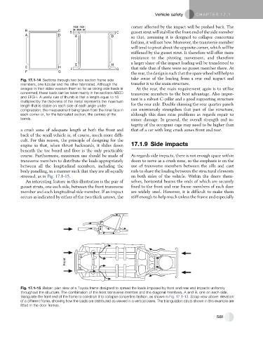
stressed, as in Fig. 17.1-15. on both sides of the vehicle. Within the doors them-
An interesting feature in this illustration is the pair of selves, horizontal beams the ends of which are securely
gusset struts, one each side, between the front transverse fixed to the front and rear frame members of each door
member and each longitudinal side member. If an impact are widely used. However, it is difficult to make them
occurs as indicated by either of the two thick arrows, the stiff enough to help much unless the frame and especially
B
Front
A
Fig. 17.1-15 Below: plan view of a Toyota frame designed to spread the loads imposed by front and rear end impacts uniformly
throughout the structure. The combination of the front transverse member and the diagonal members, A and B, one on each side,
triangulate the front end of the frame to constrain it to collapse concertina fashion, as shown in Fig. 17.1-13. Scrap view above: elevation
of a different frame, showing how the loads are distributed as viewed in a vertical plane. The triangulation struts shown in this example are
fitted in the door frames.
581