
Page 586 - Automotive Engineering Powertrain Chassis System and Vehicle Body
P. 586
Design and material utilization C HAPTER 18.1
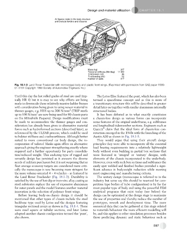
All figures relate to the body structure
and exclude fenders and closures
Mass (kg) 307
Torsional stiffness (Nm/deg) 17 360
First torsion (Hz) 36
First bending (Hz) 52
Number of parts 317
Fig. 18.1-3 Land Rover Freelander with monocoque body and plastic front wings. (Reprinted with permission from SAE paper 1999-
01-3181 Copyright 1999 Society of Automotive Engineers Inc.)
Until this day the hot rolled grades of steel are used (typ- The Lotus Elise featured the punt, which has also been
ically HR 4) but it is easy to see why efforts are being termed a spaceframe concept and as this is more of
made to downscale these relatively massive ladder frames a transitionary structure this will be described in greater
with consideration being given to using newer material in detail later on together with similar aluminium internally
2
thinner gauges, e.g. HSS up to 300 N/mm (TRIP steels structured bodies.
2
up to 590 N/mm are now being used for 80 chassis parts It has been debated as to what exactly constitutes
on the Mitsubishi Paquera). Design modifications must a chassis-less design as various forms can incorporate
be made to accommodate the thinner gauges and con- some features of the original underframe, e.g. subframes
sideration has already been given to alternative material and longitudinal/sidemember sections. Engineers such as
4
forms such as hydroformed sections (described later), as Garrett claim that the ideal form of chassis-less con-
referenced by the ULSAB process, which could be used struction emerged in the 1940s with the launching of the
to bolster stiffness and crashworthiness. Although better Austin A30 as shown in Fig. 18.1-5.
suited to more conventional car body design, the in- They would argue that using their aircraft design
corporation of tailored blanks again offers an alternative principles they were able to incorporate all the essential
approach giving the engineer strengthening exactly where load bearing requirements into a relatively lightweight
required and a further opportunity for parts consolida- body without even building in partial box sections that
tion/reduced weight. This enduring type of rugged and were featured in ‘integral’ or ‘unitary’ designs, with
versatile design has persisted as it answers the diverse elements of the chassis incorporated in the underbody.
needs of military purchasers but it is not surprising that as However, even with such box sections and subframes the
fleet average economy targets are considered more criti- easily spot welded and finished bodies provided a signi-
cally the monocoque is now becoming more stringent for ficant advance in bodyweight reduction while meeting
the more volume-oriented 4 4 vehicles – as featured by most engineering and manufacturing criteria.
the Land Rover Freelander (Fig. 18.1-3). Durability is The unitary design (monocoque is referred to in the
satisfied by the use of hot-dip or iron–zinc alloy coating as industry but some say this should be reserved for com-
steel substrates replace the use of expensive aluminium petition type bodies of tube configuration) is by far the
for outer panels and the model features another material most popular type of body and using the powerful FEM
innovation in the selection of polymer front wings. analytical programs that exist today (see below) the
Before leaving body-on-chassis design it should be design can be optimized at the design stage to maximize
mentioned that other types of chassis include the steel the use of properties and thereby reduce the number of
backbone type used by Lotus and the designs featuring prototypes, rework and development time. The more
triangular sectional arrays as shown in Fig. 18.1-4. These numerical data that can be gathered at this stage related
were steel square or tubular sections, and later Lotus to materials behaviour the more efficient modelling will
adopted another chassis configuration termed the ‘punt’, be, and this applies to other simulation processes besides
also shown. those predicting dynamic and static behaviour such as
597