
Page 588 - Automotive Engineering Powertrain Chassis System and Vehicle Body
P. 588
Design and material utilization C HAPTER 18.1
Fig. 18.1-4 (contd).
impact and torsional stiffness (demonstrated later). computer-aided drafting. However, because the small
Forming is the obvious example but the complexity of size of the elements usually prevents an overall view, and
accurately predicting thin shell behaviour during pressing the automation of the analysis tend to mask the signifi-
brings in other variables as well as mechanical properties cance of the major structural scantlings, there is a temp-
including friction, lubrication and topography. tation to by-pass the initial stages in structural design and
perform the structural analysis on a structure which has
been conceived purely as an envelope for the electro-
18.1.3 Finite element analysis mechanical systems, storage medium, passengers and
cargo, rather than an optimized load-bearing structure.
For those readers requiring some basic understanding of However, as well as fine-mesh analysis which gives an
FEA which is now a standard feature of computer-aided accurate stress and deflection prediction, course-mesh
design (CAD) procedures used by body designers the analysis can give a degree of structural feel useful in the
following extract is presented from the publication later stages of conceptual design, as well as being a vital
‘Lightweight Electric/Hybrid Design’ by Hodkinson and tool at the immediate pre-production stage.
Fenton. 5 One of the longest standing and largest FEA software
This computerized structural analysis technique has houses is PAFEC who have recommended a logical ap-
become the key link between structural design and proach to the analysis of structures, Fig. 18.1-6. This is
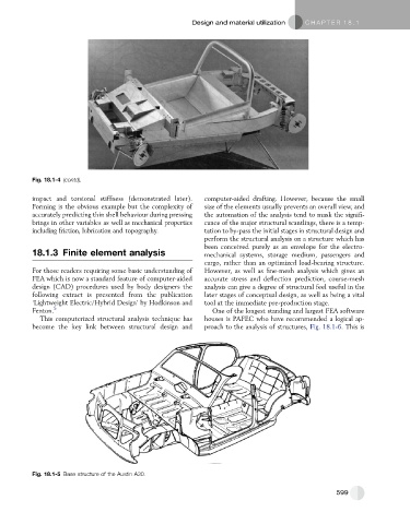
Fig. 18.1-5 Base structure of the Austin A30.
599