
Page 591 - Automotive Engineering Powertrain Chassis System and Vehicle Body
P. 591
CHAP TER 1 8. 1 Design and material utilization
In the next stage, projected torsional and bending the key parameters for obtaining a convergency of mode
stiffnesses are input as well as the dynamic frequencies in shape and natural frequency.
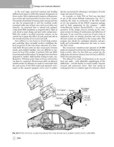
these modes. More sophisticated programs will generate An example car body FEA at Ford was described
new section and panel properties to meet these criteria. at one of the recent Boditek conferences, Fig. 18.1-7,
The inertias of mechanical running units, seating and trim outlining the steps in production of the FEA model
can also be programmed in and the resulting model at (a). An extension of the PDGS computer package
examined under special load cases such as pot-hole road used in body engineering by the company – called
obstacles. As structural data is refined and updated, Finite-Element Analysis System(FAST) – can use the
a fine-mesh FEA simulation is prepared which takes in geometry of the design concept existing on the com-
such detail as joint design and spot-weld configuration. puter system for fixing of nodal points and definition of
With this model a so-called sensitivity analysis can be elements. It can check the occurrence of such errors as
carried out to gauge the effect of each panel and rail on duplicated nodes or missing elements and even when
the overall behaviour of the structural shell. element corners are numbered in the wrong order. The
Joint stiffness is a key factor in vehicle body analysis program also checks for misshapen elements and gen-
and modelling them normally involves modifying the erally and substantially compresses the time to create
local properties of the main beam elements of a struc- the FEA model.
tural shell. Because joints are line connections between The researchers considered that upwards of 20 000
panels, spot-welded together, they are difficult to rep- nodes are required to predict the overall behaviour of the
resent by local FEA models. Combined FEA and EMA body-in-white. After the first FEA was carried out, the
(experimental modal analysis) techniques have thus been deflections and stresses derived were fed back to PDGS-
proposed to ‘update’ shell models relating to joint con- FAST for post-processing.
figurations. Vibrating mode shapes in theory and practice This allowed the mode of deformation to be viewed
can thus be compared. Measurement plots on physical from any angle – with adjustable magnification of the
models excited by vibrators are made to correspond with deflections – and the facility to switch rapidly between
the node points of the FEA model and automatic tech- stressed and unstressed states. This was useful in
niques in the computer program can be used to update studying how best to reinforce part of a structure which
Boot luggage
Roof luggage Towing
Door check
Front and
rear seat
Powertrain
passengers
Towing (b)
(a)
(c)
Fig. 18.1-7 FEA of Ford car: (a) steps in producing FEA model; (b) load inputs; (c) global model for body-in-white (BIW).
602