Page 589 - Automotive Engineering Powertrain Chassis System and Vehicle Body
P. 589

CHAP TER 1 8. 1       Design and material utilization


                                                                    Stress
                                          12 element     24 element
                                            mesh           mesh
                                                                                 Mesh 1 – 48  Elements
                                                                                 Mesh 2 – 100 Elements
                                                                                 Mesh 3 – 192 Elements
                                     Hook                                        Mesh 4 – 24  Elements
                                    pressure     48 Element                      Mesh 5 – 12  Elements
                                                   mesh
                                     loading
                               (a)                                                      MES 3 and 4
                                                                                       almost coincident
                                         100 Element    192 Element                     Node position
                                            mesh          mesh
                                                                    (c)
                                    (b)
                                                             y
                                               0        σ x
                                s ix        b i   c i
                                                                        c j  s my  c i
                                s jx        b j  0  c j  σ y
                                s mx        b m  0  c m  τ xy                     s mx
                                       1                                    m
                                     =–
                                       2
                                s iy        0  c i  b i                       σ y
                                                                  b j                    s jy
                                                                                                 b i
                                            0  c j  b j                           σ x
                                s jy
                                                                          τ xy
                                            0  c m  b m                               j
                                s my
                                                                                          s jx
                                                                      i
                                                                  s ix                          b m
                                         σ
                                             T
                                (d)   S = C  = B σ
                                                                              c m
                                                                  s iy
                                                                                                x
                                                               3               1  2              1
                                   Axial           Planar
                                                               3            2     4             2
                               (e)                Repetitive
                                    Cyclic                                                      (g)
                                                                 σ                 σ
                               Shape    Type           Geometry
                               Point    Mass
                               Line     Spring, beam, spar, gap      Bilinear           Multilinear
                                                                               ε                 ε
                               Area     2D solid, axisymmetric
                                        solid, plate                                            (h)
                               Curved area  Shell
                               Volume   3D solid
                              (f)
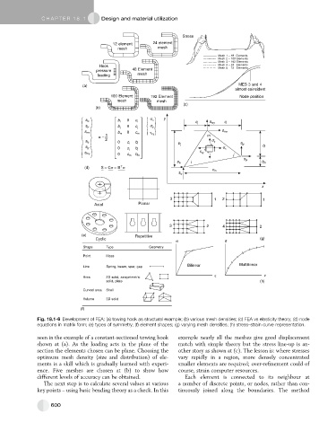
               Fig. 18.1-6 Development of FEA: (a) towing hook as structural example; (b) various mesh densities; (c) FEA vs elasticity theory; (d) node
               equations in matrix form; (e) types of symmetry; (f) element shapes; (g) varying mesh densities; (h) stress–strain curve representation.

               seen in the example of a constant-sectioned towing hook  example nearly all the meshes give good displacement
               shown at (a). As the loading acts in the plane of the  match with simple theory but the stress line-up is an-
               section the elements chosen can be plane. Choosing the  other story as shown at (c). The lesson is: where stresses
               optimum mesh density (size and distribution) of ele-  vary rapidly in a region, more densely concentrated
               ments is a skill which is gradually learned with experi-  smaller elements are required; over-refinement could of
               ence. Five meshes are chosen at (b) to show how    course, strain computer resources.
               different levels of accuracy can be obtained.        Each element is connected to its neighbour at
                 The next step is to calculate several values at various  a number of discrete points, or nodes, rather than con-
               key points – using basic bending theory as a check. In this  tinuously joined along the boundaries. The method


                    600
   584   585   586   587   588   589   590   591   592   593   594