
Page 226 - Battery Reference Book
P. 226
18/10 Lead-acid secondary batteries
The combined effects of 4, 5 and 6 means that a specifications. For comparison purposes the character-
properly matched starter motor can crank the engine istics of a 12-plate flooded battery are superimposed.
faster at low temperatures while in most cases drawing The test requires that after 30 s of discharge at, say,
a smaller current from the battery. This is a very 440A the voltage must be 7.2V or more. It can be
important feature, which enables a further stage of clearly seen that, for batteries having the same rating
system optimization to take place. on this basis, the recombination electrolyte battery has
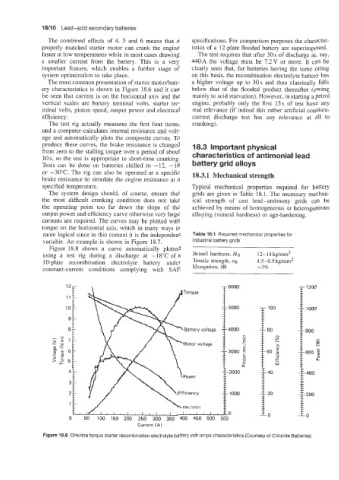
The most common presentation of starter motorhatt- a higher voltage up to 30s and then classically falls
ery characteristics is shown in Figure 18.6 and it can below that of the flooded product thereafter (owing
be seen that current is on the horizontal axis and the mainly to acid starvation). However, in starting a petrol
vertical scales are battery terminal volts, starter ter- engine, probably only the first 15s of test have any
minal volts, pinion speed, output power and electrical real relevance (if indeed this rather artificial constant-
efficiency. current discharge test has any relevance at all to
The test rig actually measures the first four items, cranking).
and a computer calculates internal resistance and volt-
age and automatically plots the composite curves. To
produce these curves, the brake resistance is changed 18.3 Important physical
from zero to the stalling torque over a period of about
10s, so the test is appropriate to short-time cranking. characteristics of antimonial lead
Tests can be done on batteries chilled to -12, -18 battery grid alloys
or -30°C. The rig can also be operated at a specific 18.3.1 Mechanical strength
brake resistance to simulate the engine resistance at a
specified temperature. Typical mechanical properties required for battery
The system design should, of course, ensure that grids are given in Table 18.1. The necessary mechan-
the most difficult cranking condition does not take ical strength of cast lead-antimony grids can be
the operating point too far down the slope of the achieved by means of homogeneous or heterogeneous
output power and efficiency curve otherwise very large alloying (natural hardness) or age-hardening.
currents are required. The curves may be plotted with
torque on the horizontal axis, which in many ways is
more logical since in this context it is the independent Table 18.1 Required mechanical properties for
variable. An example is shown in Figure 18.7. industrial battery grids
Figure 18.8 shows a curve automatically plotted
using a test rig during a discharge at -18°C of a Brinell hardness, HB 12-14kg/mm2
10-plate recombination electrolyte battery under Tensile strength, CJB 4.5-6.5 kg/mm2
Current (A) I~
constant-current conditions complying with SAE Elongation, 83 r3%
100
80
z
I
I
>
60 ,G
._
+
L
W
40
20
0 50 100 150 200 250 300 350 400 450 500 550 0
Figure 18.6 Chloride torque starter recombination electrolyte battery volt-amps characteristics (Courtesy of Chloride Batteries)