
Page 231 - Battery Reference Book
P. 231
Lead alloy development in standby (stationary) batteries 18/15
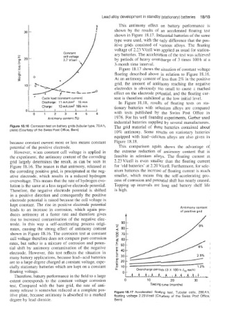
p. This antimony effect on battery performance is
shown by the results of an accelerated floating test
shown in Figure 18.17. Industrial batteries of the same
type were used, with the only difference that the pos-
itive grids consisted of various alloys. The floating
voltage of 2.23 Vlcell was applied as usual for station-
ary batteries. The acceleration of the test was achieved
by periods of heavy overcharge of 3 times 100 h at a
3-month time interval.
Figure 18.17 shows the situation of constant voltage
floating described above in relation to Figure 18.16.
At an antimony content of less than 2% in the positive
grid, the amount of antimony reaching the negative
electrodes is obviously too small to cause a marked
effect on the electrode potential. and the floating cur-
Cycle load (constant current) rent is therefore stabilized at the low initial Bevel.
Discharge: 11 mA/cmZ 15 rnin In Figure 18.18, results of floating tests on sta-
Charge: 10 mA/cm2 165 min tionary batteries with selenium alloys are compared
0
0 1 2 3 4 5 6 with tests published by the Swiss Post Office in
Antimony content I%) 1976. For his well founded experiments, Gerber used
industrial batteries supplied by several manufacturers.
Figure 18.16 Corrosion test on battery grids (tubular type, 70Ah, The grid material of these batteries contained about
plate) (Courtesy of the Swiss Post Office, Bern)
10% antimony. Some results on stationary batteries
equipped with lead-calcium alloys are also given in
because constant current more or less means constant Figure 18.18.
potential of the positive electrode. This comparison again shows the advantage of
However, when constant cell voltage is applied in the extreme reduction of antimony content that is
the experiment, the antimony content of the corroding feasible in selenium alloys. The floating current at
grid largely detenxines the result, as can be seen in 2.23Vkell is even smaller than the floating current
Figure 18.16. The reason is that antimony, released at for ‘old batteries’ at 2.20 Vkell. Furthermore, for sele-
the corroding positive grid, is precipitated at the neg- nium batteries the increase of floating current is much
ative electrode, which results in a reduced hydrogen smaller, which means that the self-accelerating pro-
overvoltage. This means that the rate of hydrogen evo- cess of corrosion and potential shift has nearly ceased.
lution is the same at a less negative electrode potential. Topping up intervals are long and battery shelf life
Therefore, the negative electrode potential is shifted is high.
in a positive direction and consequently the positive
electrode potential is raised because the cell voltage is
kept constant. The rise in positive electrode potential Antimony conteni
leads to an increase in corrosion, which again pro- of positive grid
duces antimony at a faster rate and therefore gives
rise to increased contamination of the negative elec-
trode. In this way a self-accelerating process origi-
nates, causing the strong effect of antimony content
shown in Figure 18.16. The corrosion test at constant
cell voltage therefore does not compare pure corrosion
rates, but rather is a mixture of corrosion and poten-
tial shift by antimony contamination of the negative
electrode. However, this test reflects the situation in
many battery applications, because lead-acid batteries
are to a large degree charged at constant voltage, espe-
cially stationa-y batteries which are kept on a constant
floating voltage. Overcharge periods (3 X 100 h each)
Therefore, battery performance in the field to a large
extent corresponds to the constant voltage corrosion 0 10 20 35
test. Compared with the bare grid, the rate of anti- Testing time [months)
mony release is somewhat reduced at a complete pos- Figure 18.17 Accelerated floating test. Tubular cells, 280A h,
itive plate; because antimony is absorbed to a marked floating voltage 2.23V/cell (Courtesy of the Swiss Post Office,
degree by lead dioxide. Bern)