
Page 233 - Battery Reference Book
P. 233
Separators for lead-acid automotive batteries 18/17
Table 18.3 Typical properties of separators for non-antimonial lS5O r
automotive batteries
Microporous Sintered
polyethylenes PVC
Electrical resistance (mR/cm2) 1.4-1.8 2.5-3.5
Backweb thickness (mm) 25 25-35
Acid displacement (cm3/m2) 146 25 0
Porosity (%) 55 35 1.26 t
Oxidation resistance Good Good
Maximum pore siLe (Fm) 10.1 24
Flexibility Good Poor 1 2 3 4 5
Sealability Good Satisfactory Separator electrical resistance (ma cm2)
Chemical pur;ty Good Good
Cold voltage -3O"C/30 s (V) 8.76 1.98 Figure 18.21 -30°C cold cranking performance: effect of separ-
ator electrical resistance. 30s cell voltage at 210A: 9-plate
calcium alloy single cells, SAE J-537; test procedure (Courtesy of
W. R. Groce)
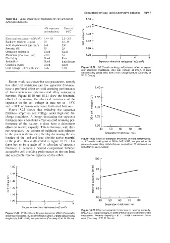
Recent work has shown that two parameters, namely
low electrical resistance and low separator thickness,
have a profound effect on cold cranking performance
of low-maintenance calcium-lead alloy automotive -
batteries. Figure 18.20 and 18.21 show the beneficial -
> 1.35
effect of decreasing the electrical resistance of the
separator on the cell voltage in tests run at -18°C
and -30°C on low-maintenance lead-acid batteries.
Figure 18.22 shows that reducing the separator
thickness improves cell voltage under high-rate dis-
charge conditions. Although decreasing the separator
thickness has a beneficial effect on cold cranking per-
formance of the battery, it does have a deleterious 1.20 u
effect on reserve capacity. This is because, with thin-
50
60
70
ner separators, the volume of sulphuric acid adjacent 40 Separator thickness (mi is 1 80
to the plates is diminished, thereby decreasing the uti-
lization of the lead and lead dioxide active material Figure 18.22 Effect of separator thickness on cold performance.
in the plates. This is illustrated in Figure 18.23. Thus -18°C cold cranking test at 280A, SAE J-537; test procedure. 9-
there has to be a trade-off in selection of separator plate antimonial alloy cells/cellulosic separators; 29 observations
thickness to achieve a desired compromise between (Courtesy of W. R. Groce)
acceptable cold cranking performance on the one hand
and acceptable reserve capacity on the other.
1.50 r
1.44 c
0, 5 851
a
1.26
80
1.20 I I I I 40 50 60 70 80
1 2 3 4 5 Separator thickness (mil)
Separator electrical resistance (ma cm2)
Figure 18.23 Effect of separator thickness on reserve capacity,
Figure 18.20 18°C cold cranking perforinance: effect of separator SAE J-537; test procedure, 9-plate antimonial alloy cells/cellulosic
electrical resistance. 30 s cell voltage at 280 A, 9 plate calcium alloy separators. Reserve capacity = 87.1 + 0.096 x separator thick-
single cells SAE J-537; test procedure (Courtesy of W. R. Groce) ness (Courtesy of W. R. Groce)