
Page 64 - Bebop to The Boolean Boogie An Unconventional Guide to Electronics Fundamentals, Components, and Processes
P. 64
Using Transistors to Build Primitive Logic ~ ~ ~ ~ ~ i ~ n s
Y
NOT +I+ 10
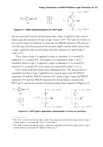
Figure 6-1 CMOS Implementation of a NOT gate
as an actiue-low3 control, which means that a logic 0 applied to the control
input turns the transistor ON and a logic I turns it OFF. The lack of a bobble on
the control input of transistor Tr, indicates an NMOS transistor. The lack of
a bobble says that this transistor has an actiue-high4 control, which means that
a logic 1 applied to the control input turns the transistor ON and a logic 0
turns it OFF.
Thus, when a logic 0 is applied to input a, transistor Tr, is turned ON,
transistor Tr, is turned OFF, and output y is connected to logic 1 via Tr,.
Similarly, when a logic 1 is applied to input a, transistor Tr, is turned OFF,
transistor Tr, is turned ON, and output y is connected to logic 0 via Tr,.
Don’t worry if all this seems a bit confusing at first. The main points to
remember are that a logic 0 applied to its control input turns the PM
transistor ON and the NMOS transistor OFF, while a logic 1 turns the
transistor OFF and the NMOS transistor ON. It may help to visualize the
NOT gate’s operation in terms of switches rather than transistors (Figure 6-2).
Figure 6-2. NOT gate’s operation represented in terms of switches
3 The “low” comes from the fact that, under the commonly used positive-logic system, logic 0
is more negative (conceptually “lower”) than logic I.
4 The “high” comes from the fact that, under the commonly used positive-logic system, logic I
is more positive (conceptually “higher”) than logic 0.