
Page 67 - Bebop to The Boolean Boogie An Unconventional Guide to Electronics Fundamentals, Components, and Processes
P. 67
48 Chaptersix
ii”
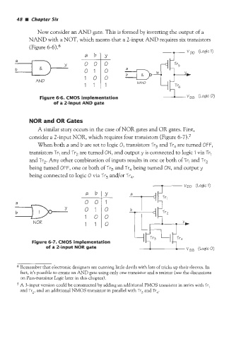
Now consider an AND gate. This is formed by inverting the output of a
NAND with a NOT, which means that a 2-input AND requires six transistors
(Figure 6-6).6
AND 100
Figure 6-6. CMOS implementation
of a 2-input AND gate
NOR and OR Gates
A similar story occurs in the case of NOR gates and OR gates. First,
consider a 2-input NOR, which requires four transistors (Figure 6-7).7
When both a and b are set to logic 0, transistors Tr, and Tr4 are turned OFF,
transistors Trl and Tr, are turned ON, and output y is connected to logic 1 via Tr,
and Tr,. Any other combination of inputs results in one or both of Tr, and Tr,
being turned OFF, one or both of Tr, and Tr, being turned ON, and output y
being connected to logic 0 via Tr, and/or Tr4.
NOR 1 110
Figure 6-7. CMOS implementation
of a 2-input NOR gate
vS5 (LogicO)
6 Remember that electronic designers are cunning little devils with lots of tricks up their sleeves. In
fact, it’s possible to create an AND gate using only one transistor and a resistor (see the discussions
on Puss-trunsistor Logic later in this chapter).
7 A 3-input version could be constructed by adding an additional PMOS transistor in series with Tr,
and Tr,, and an additional NMOS transistor in parallel with Tr, and Tr,.