
Page 66 - Bebop to The Boolean Boogie An Unconventional Guide to Electronics Fundamentals, Components, and Processes
P. 66
":: 'DD (Logicl)
Using TrmSiStovS to Build Primitive Logic Fcmctions
NAND 101
1 1
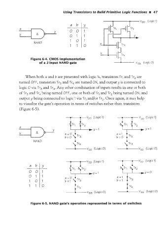
Figure 6-4. CMOS implementation
of a Zinput NAND gate (Logic 0)
'When both a and b are presented with logic Is, transistors Tr, and Tr, are
turned OFF, transistors Tr3 and Tr, are turned ON, and output y is connected to
logic 0 via Tr3 and Tr,. Any other combination of inputs results in one or both
of Tr, and Tr, beiing turned OFF, one or both of Trl and Tr, being turned ON, and
output y being connected to logic 1 via Tr, and/or Tr,. Once again, it may help
to visualize the gate's operation in terms of switches rather than transistors
(Figure 6-5).
-
Y
a 1 Tr3
b=O
NAND
---L---vS5 (Logic 0)
VDD (Logicl)
a=O
Figure 6-5. NAND gate's operation represented in terms of switche