
Page 65 - Bebop to The Boolean Boogie An Unconventional Guide to Electronics Fundamentals, Components, and Processes
P. 65
46 4 Chaptersix
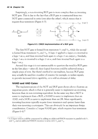
Surprisingly, a non-inverting BUF gate is more complex than an inverting
NOT gate. This is due to the fact that a BUF gate is constructed from two
NOT gates connected in series (one after the other), which means that it
requires four transistors (Figure 6-3).
a Y
BUF
Figure 6-3. CMOS implementation of a BUF gate
The first NOT gate is formed from transistors Tr, and Tr2, while the second
is formed from transistors Tr, and Tr4. A logic 0 applied to input a is inverted to
a logic 1 on w, and then inverted back again to a logic 0 on output y. Similarly,
a logic I on a is inverted to a logic O on w, and then inverted back again to a
logic 1 on y.
Around this stage it is not unreasonable to question the need for BUF gates
in the first place-after all, their logical function could be achieved using a
simple piece of wire. But there’s method to our madness, because BUF gates
may actually be used for a number of reasons: for example, to isolate signals,
to provide increased drive capability, or to add an element of delay.
NAND and AND Gates
The implementations of the NOT and BUF gates shown above illustrate an
important point, which is that it is generally easier to implement an inverting
function than its non-inverting equivalent. In the same way that a NOT is
easier to implement than a BUF, a NAND is easier to implement than an
AND, and a NOR is easier to implement than an OR. More significantly,
inverting functions typically require fewer transistors and operate faster than
their non-inverting counterparts. This can obviously be an important design
consideration. Consider a 2-input NAND gate, which requires four transistors
(Figure 6-4).5
5 A 3-input version could be constructed by adding an additional PMOS transistor in parallel with Tr,
and Tr2, and an additional NMOS transistor in series with Tr, and Tr4