
Page 69 - Bebop to The Boolean Boogie An Unconventional Guide to Electronics Fundamentals, Components, and Processes
P. 69
The NOT gate would be constructed in the standard way using two
transistors as described above, but the XNOR differs from the previous gates
in the way that transistors Tr, and Tr, are utilized. First, consider the case where
input b is presented with a logic 0: transistor Tr, is turned OFF, transistor Tr,
is turned ON, and output y is connected to the output of the NOT gate via Tr3.
Thus, when input b is logic 0, output y has the inverse of the value on input a.
Now consider the case where input b is presented with a logic 1: transistor Tr,
is turned OFF, transistor Tr, is turned ON, and output y is connected to input a
via Tr, Thus, when input b is logic 1, output y has the same value as input a.
The end result of all these machinations is that wiring the transistors together
in this way does result in a function that satisfies the requirements of the
XNOR truth table.
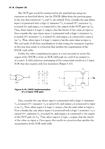
Unlike the other complementary gates, it is not riecessary to invert the
output of the XNOR to form an XOR (although we could if we wanted to,
of course). A little judicious rearranging of the components results in a 2-input
XOR that also requires only four transistors (Figure 4-10).
- 000 Y,
a
01 1
b
XOR
Figure 6-1 0. CMOS implementation b
of a 2-input XOR gate
First, consider the case where input b is presented with a logic 0: transistor
Tr, is turned OFF, transistor Tr, is turned ON, and output y is connected to input
a via Tr,. Thus, when input b is logic 0, output y has the same value as input a.
Now consider the case where input b is presented with a logic 1: transistor Tr, is
turned OFF, transistor Tr, is turned ON, and output y is connected to the output
of the NOT gate via Tr4 Thus, when input b is logic 1, output y has the inverse
of the value on input a. Once again, this results in a junction that satisfies the
requirements of the XOR truth table.