
Page 142 - 02. Subyek Computer Aided Design - Beginner’s Guide to SOLIDWORKS 2019- Level 1 by Alejandro Reyes
P. 142
Part Modeling
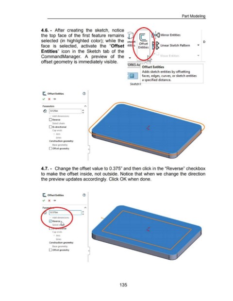
4.6. - After creating the sketch, notice
I
the top face of the first feature remains :ca Mirror Entities
I
selected (in highlighted color); while the D
Offset
face is selected, activate the "Offset Entities ~ linear Sketch Pattern
Entities" icon in the Sketch tab of the
CommandManager. A preview of the r 1o e Ent1t1es
offset geometry is immediately visible.
RKS Ac' Offset Entities
Adds sketch entities by offsetting
2:QJ faces, edges, curves, or sketch entities
a specified distance.
Sketchl
(C.. Offset Entities
~ X ....,.
Parameters
~ I 0.125in
Add dimensions
0 Reverse
Select chain
0 Bi-directional
Cap ends
Arcs
lines
Construction geometry:
Base geometry
0 Offset geometry
4.7.- Change the offset value to 0.375" and then click in the "Reverse" checkbox
to make the offset inside, not outside. Notice that when we change the direction
the preview updates accordingly. Click OK when done.
(C.. Offset Entities
~ X ....,.
1\
L-----~....._______J "'
Add dimensions
0 Reverse ~"-.
Select c~
nal
Cap ends
Arcs
lines
Construction geometry:
Base geometry
0 Offset geometry 0
135