
Page 144 - 02. Subyek Computer Aided Design - Beginner’s Guide to SOLIDWORKS 2019- Level 1 by Alejandro Reyes
P. 144
Part Modeling
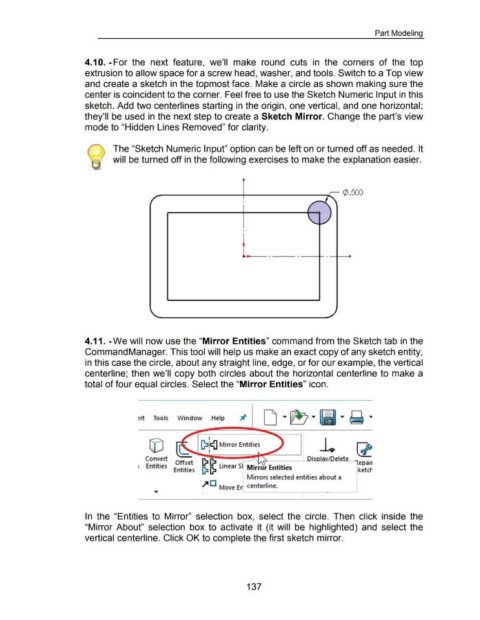
4.1 0. -For the next feature, we'll make round cuts in the corners of the top
extrusion to allow space for a screw head, washer, and tools. Switch to a Top view
and create a sketch in the topmost face. Make a circle as shown making sure the
center is coincident to the corner. Feel free to use the Sketch Numeric Input in this
sketch. Add two centerlines starting in the origin, one vertical, and one horizontal;
they'll be used in the next step to create a Sketch Mirror. Change the part's view
mode to "Hidden Lines Removed" for clarity.
The "Sketch Numeric Input" option can be left on or turned off as needed. It
will be turned off in the following exercises to make the explanation easier.
¢ . 500
.f
/
r
I
I
- - -
4.11. -We will now use the "Mirror Entities" command from the Sketch tab in the
Command Manager. This tool will help us make an exact copy of any sketch entity,
in this case the circle, about any straight line, edge, or for our example, the vertical
centerline; then we'll copy both circles about the horizontal centerline to make a
total of four equal circles. Select the "Mirror Entities" icon.
~rt Tools Window Help
I
[}:1!1{1 Mirror Entities
I
Convert (}:1 (}:1 _ DisolavJDelete
Entities Offset (}:1 (}:I linear Sl Mirror Entities "'lepair
Entities rketct
Mirrors selected entities about a
.,. D Move Er centerline. I
In the "Entities to Mirror" selection box, select the circle. Then click inside the
"Mirror About" selection box to activate it (it will be highlighted) and select the
vertical centerline. Click OK to complete the first sketch mirror.
137