
Page 146 - 02. Subyek Computer Aided Design - Beginner’s Guide to SOLIDWORKS 2019- Level 1 by Alejandro Reyes
P. 146
Part Modeling
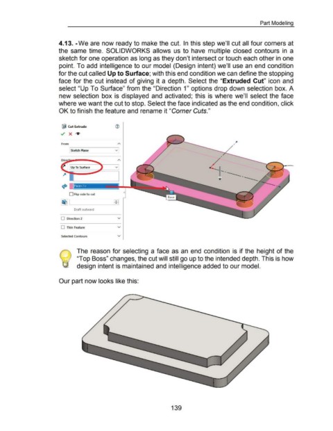
4.13. -We are now ready to make the cut. In this step we'll cut all four corners at
the same time. SOLIDWORKS allows us to have multiple closed contours in a
sketch for one operation as long as they don't intersect or touch each other in one
point. To add intelligence to our model (Design intent) we'll use an end condition
for the cut called Up to Surface; with this end condition we can define the stopping
face for the cut instead of giving it a depth. Select the "Extruded Cut" icon and
select "Up To Surface" from the "Direction 1" options drop down selection box. A
new selection box is displayed and activated; this is where we'll select the face
where we want the cut to stop. Select the face indicated as the end condition, click
OK to finish the feature and rename it "Corner Cuts."
Qijl Cut-Extrude
../ X IV'
From
Sketch Plane v
Up To Surface v
..... ___
'•
Face< 1 >
D Flip side t o cut
~ I EEl
Draft outward
D Direction 2 v
D Thin Feature v
Selected Contours v
The reason for selecting a face as an end condition is if the height of the
"Top Boss" changes, the cut will still go up to the intended depth. This is how
design intent is maintained and intelligence added to our model.
Our part now looks like this:
139