
Page 169 - 02. Subyek Computer Aided Design - Beginner’s Guide to SOLIDWORKS 2019- Level 1 by Alejandro Reyes
P. 169
Part Modeling
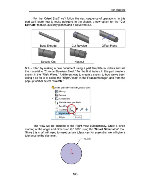
For the 'Offset Shaft' we'll follow the next sequence of operations. In this
part we'll learn how to make polygons in the sketch, a new option for the "Cut
Extrude" feature, auxiliary planes and a Revolved cut.
Boss Extrude Cut Revolve Offset Plane
Second Cut Hex cut
5.1. - Start by making a new document using a part template in Inches and set
the material to "Chrome Stainless Steel." For the first feature in this part create a
sketch in the "Right Plane." A different way to create a sketch to how we've been
doing it so far is to select the "Right Plane" in the FeatureManager, and from the
pop-up toolbar select "Sketch."
~ Part3 (Default<< Default> _Display StatE
~ History
~ Sensors
~ [A I Annotations
o-
8=i Material <not specified>
CD Front Pia
CD Top Pia PJ
[!] Right Plan .,.._..
L Origin r-=-S-ke-tch-,
The view will be oriented to the Right view automatically. Draw a circle
starting at the origin and dimension it 0.600" using the "Smart Dimension" tool.
Since this shaft will need to meet certain tolerances for assembly, we will give a
tolerance to the diameter.
,..--- (/) . 600
163