Page 173 - 02. Subyek Computer Aided Design - Beginner’s Guide to SOLIDWORKS 2019- Level 1 by Alejandro Reyes
P. 173

Part Modeling


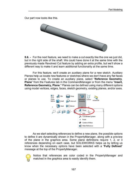
                                                      Our part now looks like this.


                                                      5.6. - For the next feature, we need to make a cut exactly like the one we just did,


                                                      but in the right side of the shaft. We could have done it at the same time with the


                                                      previously made Revolved Cut feature by adding an extra profile, but we'll show a


                                                      different way to make it and learn additional functionality at the same time.


                                                                        For this feature, we'll create an  auxiliary plane for a new sketch. Auxiliary


                                                      Planes help us locate new features or sketches where we don't have any flat faces


                                                      or  planes  to  use.  To  create  an  auxiliary  plane,  select  "Reference  Geometry,


                                                      Plane" from the Features tab in the Command Manager or from the menu "Insert,


                                                      Reference Geometry, Plane." Planes can be defined using many different options


                                                      using model vertices, edges, faces, sketch geometry, existing planes, and/or axes.


                                                                                                               ~ g J] Rib  ij Wrap


                                                                                                               inear  I'C\.                                                Reference  Curves
                                                                                                              •attern  !«] Draft  ctD  Intersect                           Geometry                      lnstant3D


                                                                                                                 ...       GSJ Shell  I) cJ Mirror


                                                                                                                                                                            ~ Plane

                                                                                                                                                                               ••
                                                                                                                                                                             ~  Axis


                                                                                                                                                                            )+  Coordinate System


                                                                                                                                                                             Q  Point


                                                                                                                                                                            -0  Center of Mass


                                                                                                                                                                           e@ Mate Reference


                                                                        As we start selecting references to define a new plane, the possible options


                                                      to define it are dynamically shown  in  the PropertyManager, along with a preview


                                                      of the  plane  in  the  graphics  area.  Some  plane  definitions  require  1,  2,  or  3


                                                      references  depending  on  each  case,  but  SOLIDWORKS  helps  us  by letting  us


                                                      know  when  the  necessary  options  have  been  selected  with  a  "Fully  Defined"


                                                      message at the top of the PropertyManager.


                                                                         Notice  that  references  are  color  coded  in  the  PropertyManager  and


                                                                         matched in the graphics area to easily identify them.


                                                                                                                                                           167
   168   169   170   171   172   173   174   175   176   177   178