
Page 177 - 02. Subyek Computer Aided Design - Beginner’s Guide to SOLIDWORKS 2019- Level 1 by Alejandro Reyes
P. 177
Part Modeling
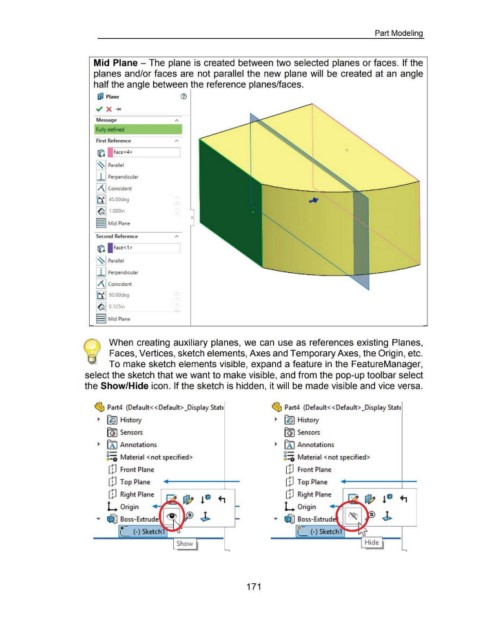
Mid Plane - The plane is created between two selected planes or faces. If the
planes and/or faces are not parallel the new plane will be created at an angle
half the angle between the reference planes/faces.
IJ;I Plane
~ x .....
Message
Fully defined
First Reference
fil i Face <4 >
~~~ Parallel
I I I Perpendicular
IAI Coincident
1~ 1 45.00deg
1<6111 000 rt
0
I I Mid Plane
Second Reference
fil Face<1>
~~~ Parallel
I I I Perpendicular
IAI Coincident
~~~90.00deg
1<611 0 12S'n
I I Mid Plane
@ When creating auxiliary planes, we can use as references existing Planes,
Faces, Vertices, sketch elements, Axes and Temporary Axes, the Origin, etc.
To make sketch elements visible, expand a feature in the FeatureManager,
select the sketch that we want to make visible, and from the pop-up tool bar select
the Show/Hide icon. If the sketch is hidden, it will be made visible and vice versa.
~ Part4 (Default<< Default> _Display StatE ~ Part4 (Default< <Default> _Display StatE
~ fl91 History ~ fl91 History
[GI Sensors rnJ Sensors
~ [A I Annotations ~ [A I Annotations
o- o-
8::0 Material <not specified> 8::0 Material <not specified>
CD Front Plane CD Front Plane
CD Top Plane [~J Top Plane
CD Right Plane CP Right Plane
L Origin L Origin
""" ~ Boss-Extrude """ ~ Boss-Extrud
l (-) Sketch1........-r (_ (-) Sketch 1.,-...-r::
Show Hide
171