
Page 171 - 02. Subyek Computer Aided Design - Beginner’s Guide to SOLIDWORKS 2019- Level 1 by Alejandro Reyes
P. 171
Part Modeling
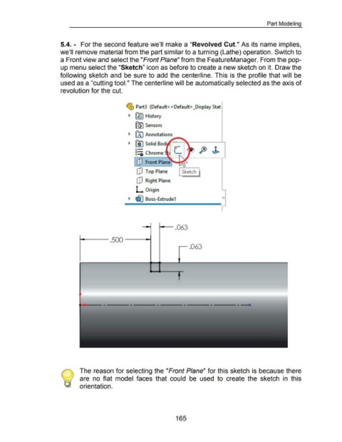
5.4. - For the second feature we'll make a "Revolved Cut." As its name implies,
we'll remove material from the part similar to a turning (Lathe) operation. Switch to
a Front view and select the "Front Plane" from the FeatureManager. From the pop-
up menu select the "Sketch" icon as before to create a new sketch on it. Draw the
following sketch and be sure to add the centerline. This is the profile that will be
used as a "cutting tool." The centerline will be automatically selected as the axis of
revolution for the cut.
~ Part3 (Default<< Default> _Display Stat
~ ~~ History
Front Plane ~?
[!] Top Plane I Sketch fl
[!] Right Plane
L Origin
Boss-Extrude1 o
_....J
....,_ ___ .500 -----t
r- .063
~---------------------------------- .
The reason for selecting the "Front Plane" for this sketch is because there
are no flat model faces that could be used to create the sketch in this
orientation.
165