
Page 482 - 02. Subyek Computer Aided Design - Beginner’s Guide to SOLIDWORKS 2019- Level 1 by Alejandro Reyes
P. 482
Assembly Modeling
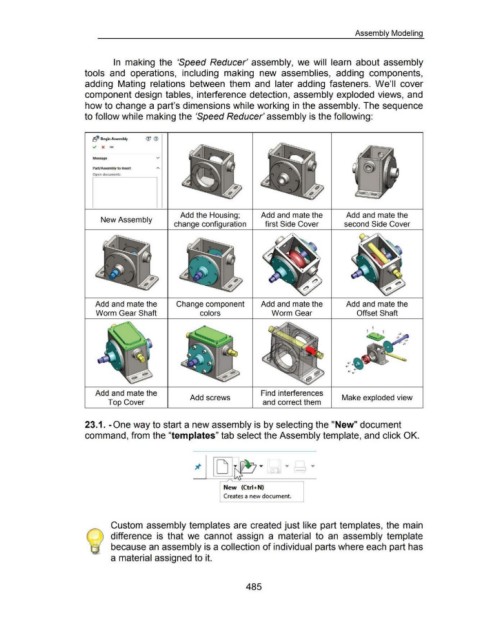
In making the 'Speed Reducer' assembly, we will learn about assembly
tools and operations, including making new assemblies, adding components,
adding Mating relations between them and later adding fasteners. We'll cover
component design tables, interference detection, assembly exploded views, and
how to change a part's dimensions while working in the assembly. The sequence
to follow while making the 'Speed Reducer' assembly is the following:
~<$ Begin Assembly <JJ <i)
~ X ...,.
v
Part/Assembly to Insert
Open documents:
Add the Housing; Add and mate the Add and mate the
New Assembly
change configuration first Side Cover second Side Cover
Add and mate the Change component Add and mate the Add and mate the
Worm Gear Shaft colors Worm Gear Offset Shaft
Add and mate the Find interferences
Add screws Make exploded view
Top Cover and correct them
23.1. -One way to start a new assembly is by selecting the "New" document
command, from the "templates" tab select the Assembly template, and click OK.
... J l ...
I
r New (Ctri+N)
Creates a new document.
Custom assembly templates are created just like part templates, the main
difference is that we cannot assign a material to an assembly template
because an assembly is a collection of individual parts where each part has
a material assigned to it.
485