Page 698 - 02. Subyek Computer Aided Design - Beginner’s Guide to SOLIDWORKS 2019- Level 1 by Alejandro Reyes
P. 698

Beginner's Guide to SOLIDWORKS 2019- Level I


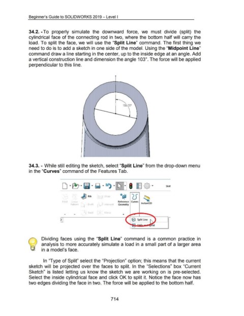
                                    34.2. -To  properly  simulate  the  downward  force,  we  must  divide  (split)  the


                                    cylindrical face  of the connecting  rod  in  two, where the bottom  half will  carry the


                                    load. To split the face,  we will  use the "Split Line"  command.  The first thing we


                                    need to do is to add a sketch in one side of the model. Using the "Midpoint Line"


                                    command draw a line starting in the center, up to the inside edge at an angle. Add


                                    a vertical construction line and dimension the angle 103°. The force will be applied


                                    perpendicular to this line.


                                    34.3. - While still editing the sketch, select "Split Line" from the drop-down menu


                                    in the "Curves" command of the Features Tab.


                                                                                                                                    rap
                                                                                         ()()  ~ Rib

                                                                              F1llet     Lmea                                                     Reference  Curves
                                                                                        Pattern              Draft               Intersect        Geometry                     lnstant30


                                                                                                             Shell                 hrror


                                                                           )


                                                    Dividing  faces  using  the  "Split  Line"  command  is  a  common  practice  in


                                                    analysis to more accurately simulate a load  in  a small part of a larger area


                                                    in a model's face.


                                                      In  "Type of Split" select the "Projection" option; this means that the current


                                    sketch  will  be  projected  over the  faces  to  split.  In  the  "Selections"  box "Current


                                    Sketch"  is  listed  letting  us  know the  sketch  we  are  working  on  is  pre-selected.


                                    Select the inside cylindrical face and click OK to split it.  Notice the face now has


                                    two edges dividing the face in two. The force will be applied to the bottom half.


                                                                                                                                         714
   693   694   695   696   697   698   699   700   701   702   703