
Page 702 - 02. Subyek Computer Aided Design - Beginner’s Guide to SOLIDWORKS 2019- Level 1 by Alejandro Reyes
P. 702
Analysis: SimulationXpress
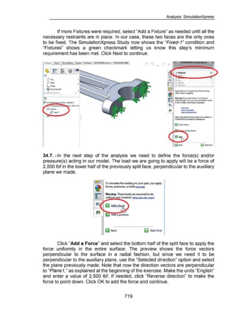
If more Fixtures were required, select "Add a Fixture" as needed until all the
necessary restraints are in place. In our case, these two faces are the only ones
to be fixed. The SimulationXpress Study now shows the "Fixed-1" condition and
"Fixtures" shows a green checkmark letting us know this step's minimum
requirement has been met. Click Next to continue.
0
dJ Top
dJ Right
L Origin
~ ~ Boss-Extrudel
1----1 Apply fixtures to keep the part from moving
""'
< > when loads are applied.
0
~ Warning: Faces with fixtures are treated as
~ perfectly rigid. This can cause unrealistic results
in the vicinity of the fixture. Examples:
F'oced Holes
F'IXecf l/S, Syp!!9!tecf
F'oced vs. AttKN<I P~ns
Note: More flexible fixture types are available in
SOLIDWORKS Simulation Professional.
~ Add a fixture
Gj Back lij Start Over
34.7. -In the next step of the analysis we need to define the force( s) and/or
pressure(s) acting in our model. The load we are going to apply will be a force of
2,500 lbf in the lower half of the previously split face, perpendicular to the auxiliary
plane we made.
To simulate the loading on your part. you apply
forces, pressures, or both.Examples
Warning: These loads are assumed to be
uniform and constant. What does this mean?
~ Back ~ Start Over
Click "Add a Force" and select the bottom half of the split face to apply the
force uniformly in the entire surface. The preview shows the force vectors
perpendicular to the surface in a radial fashion, but since we need it to be
perpendicular to the auxiliary plane, use the "Selected direction" option and select
the plane previously made. Note that now the direction vectors are perpendicular
to "Piane1," as explained at the beginning of the exercise. Make the units "English"
and enter a value of 2,500 lbf. If needed, click "Reverse direction" to make the
force to point down. Click OK to add the force and continue.
719